Rajasthan Board RBSE Class 12 Physics Chapter 10 Alternating Current
RBSE Class 12 Physics Chapter 10 Text Book Exercise with Answers
RBSE Class 12 Physics Chapter 10 Multiple Choice Type Questions
Question 1.
The rms value of alternating current is :
(a) twice of peak value
(b) half of peak value
(c) equal to peak value
(d) \(\frac{1}{\sqrt{2}}\) time of peak value
Answer:
(d) \(\frac{1}{\sqrt{2}}\) time of peak value
Root mean square value of current
Irms = \(\frac{I_{m}}{\sqrt{2}}\)
Question 2.
Which of the following is used in ac circuit which shows that the current lead the voltage at the phase:
(a) pure resistance
(b) pure inductance
(c) pure capacitor
(d) none of these
Answer:
(c) pure capacitor
Current leads the voltage in pure capacitor circuit.
Question 3.
The current lags behind the voltage by a phase different of π/2 radian, when in the circuit is :
(a) only resistance
(b) only inductance
(c) only capacitor
(d) both capacitor and resistance
Answer:
(b) only inductance
Voltage leads the current at π/2 in pure inductor circuit.
Question 4.
The unit of ωC is :
(a) Ohm
(b) mho
(c) volt
(d) ampere
Answer:
(b) mho
Question 5.
Capacitor in a circuit:
(a) passes the alternating current
(b) stops the flow of alternating current
(c) passes the direct current
(d) stops the alternating current and passes the direct current.
Answer:
(a) passes the alternating current
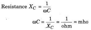
Resistance of capacitor
XC = \(\frac{1}{\omega C}=\frac{1}{2 \pi f C}\)
∵ f = 0
∴ XC = ∞
So, stop the d.c. current
Question 6.
Which of the following unit is not same
![]()
Answer:
(a)
\(\frac{1}{\sqrt{L C}}\) = Angular frequency and \(\sqrt{L C}\) or RC or \(\frac{L}{R}\) = time
Question 7.
An alternating current circuit is in resonance at 10 kHz frequency. If frequency increases to 12 kHz, then what will be effect on impedance?
(a) remains unchanged
(b) increases 1.2 times
(c) increases and becomes capacitive
(d) increases and becomes inductive
Answer:
(d) increases and becomes inductive
In the condition of resonance Z = R, so impedance is not dependent on the frequency.
Question 8.
In a circuit, the phase of the current is lagging behind π/3 angle with phase of voltage. Element present in circuit are :
(a) R and C
(b) R and L
(c) L and C
(d) only L
Answer:
(b) R and L
The voltage leads the current with the phase \(\frac{\pi}{3}\)
Question 9.
Power factor of pure inductor or pure capacitor circuit is :
(a) one
(b) zero
(c) π
(d) more than zero.
Answer:
(b) zero
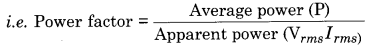
Power in circuit (P) = Vrms Irms cosϕ
= Vrms Irms Cos 90° = 0
Question 10.
How can you decrease current in an alternating current circuit without any loss of power?
(a) By using pure inductor
(b) By using pure resistance
(c) By using resistance and inductor
(d) By using resistance and capacitor
Answer:
(a) By using pure inductor
The circuit has pure inductor or capacitor.
Question 11.
Current I = \(I_{m} \sin \left(\omega t-\frac{\pi}{2}\right)\) is flowing in an ac circuit. If alternating voltage is V = Vm sin ωt, then consumed power is :
Answer:
(d)
Power (P) = Vrms Irms cosϕ
= Vrms Irms Cos 90° = 0
Question 12.
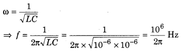
In series LCR circuit, in the condition of resonance, if C = 1 µF and L = 1 H then frequency will be :
(a) 106 Hz
(b) 2π × 106 Hz
(c) \(\frac{10^{6}}{2 \pi}\) Hz
(d) 2π × 10-6 Hz
Answer:
(c) \(\frac{10^{6}}{2 \pi}\) Hz
Question 13.
The core of the transformer is laminated, because :
(a) magnetic flux may increase
(b) the residual magnetism may reduce
(c) the magnetic susceptibility of core may increase
(d) there may be minimum energy loss due to eddy currents
Answer:
(d) there may be minimum energy loss due to eddy currents
To reduce the eddy currents.
Question 14.
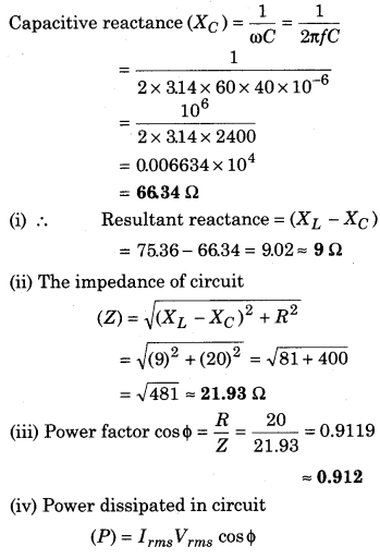
In the following figure, the point representing the condition of resonance is :
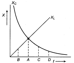
(a) A
(b) B
(c) C
(d) D
Answer:
(a) A
At resonance condition XL = XC
∴ Point ‘A’ shows condition of resonance
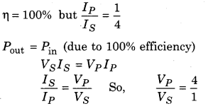
Question 15.
The ratio of current flowing across primary and secondary of a 100% efficient transformer is 1 : 4. Then what will be the ratio of voltage across primary and secondary?
(a) 1 : 4
(b) 4 : 1
(c) 1 : 2
(d) 2 : 1
Answer:
(b) 4 : 1
RBSE Class 12 Physics Chapter 10 Very Short Answer Type Questions
Question 1.
The equation of an alternating voltage is v = \(200 \sqrt{2} \sin 100 \pi t\). Find out the its root mean square value and frequency
Answer:
200 V, 50 Hz.
Question 2.
Write a relation between root mean square value and peak value of alternating current.
Answer:
Irms = \(\sqrt{2}\) Im
Question 3.
The equation of an alternating current is I = Im sin ωt. Then write alternating voltage equation in inductor circuit.
Answer:
V = Vm \(\sin \left(\omega t+\frac{\pi}{2}\right)\)
Question 4.
In an a.c. circuit, at any time voltage is V = 200 sin 314 t, then find frequency of the alternating current.
Answer:
50 Hz.
Question 5.
What will be effect on inductive reactance and capacitive reactance on increasing frequency of the alternating current?
Answer:
Inductive reactance will increase and capacitive reactance will decrease.
Question 6.
The inductance of a coil is 0.1 H. It is connected to an alternating current of 50 Hz frequency. Find out the reactance.
Answer:
31.4 Ω.
Question 7.
What will be phase difference between current and voltage for a series LCR circuit?
Answer:
Between 0 to ± \(\frac{\pi}{2}\).
Question 8.
What will be phase difference between voltage of inductance and capacitance in a series LCR resonance circuit?
Answer:
180°.
Question 9.
What will be impedance in a series LCR circuit?
Answer:
Equal to resistance.
Question 10.
What will be the value of power factor in an alternating current circuit, for inductance, capacitance and resistance?
Answer:
Zero, zero and one.
Question 11.
What is unit of VPC?
Answer:
Second.
Question 12.
If value of capacitance becomes 4 times in a series LCR circuit, then for same for same resonant frequency. what will be the value of inductance?
Answer:
∵ ω0 = \(\frac{1}{\sqrt{L C}}\)
when C increase to 4C then the value of L will be L/4
∴ \(\frac{1}{\sqrt{\frac{L}{4} \times 4 C}}=\frac{1}{\sqrt{L C}}=\omega_{0}\)
Question 13.
What will be the root mean square value of wattless current?
Answer:
I = \(\frac{I_{m}}{\sqrt{2}}\) sin θ.
Question 14.
The ratio of turns across primary and secondary in a transformer is 1 : 4. What type of this transformer is ?
Answer:
Step up.
Question 15.
Write value of wattless current in an ac circuit.
Answer:
Iwattless = Irms sinθ = \(\frac{I_{m}}{\sqrt{2}}\) sin θ.
RBSE Class 12 Physics Chapter 10 Short Answer Type Questions
Question 1.
Why does prefer the alternating current in comparison of direct current? Explain the proper cause.
Answer:
The alternating current easily convert high potential to low potential and reduced the energy loss easily.
Question 2.
Alternating current at 220 V is more dangerous than direct current of 220 V. Why?
Answer:
220 V a.c. means the effective or virtual valve of a.c. is 220 V i.e., Vrms = \(\sqrt{2}\) Vrms
As peak valve, V0 = \(\sqrt{2}\) Vrms
= 1.414 × 220 = 311 volt
But 220 V d.c. has the same peak valve (i.e., 220 V). Moreover the shock of a.c. is attractive and that of d.c. is repulsive.
Hence 220 V a.c. is more dangerous than 220 volt d.c.
Question 3.
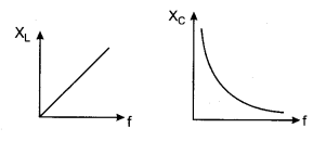
Draw a graph between inductive reactance and capacitive reactance with frequency.
Answer:
Inductive reactance (XL) = 2πfL
Question 4.
Capacitor blocks direct current but easily passes alternating current. Why?
Answer:
Capacitive reactance (XC) = \(\frac{1}{2 \pi f C}\)
But for d.c., f = 0
∴ XC = \(\frac{1}{0}\) = ∞
∴Capacitor have infinite resistance for direct currents.
Question 5.
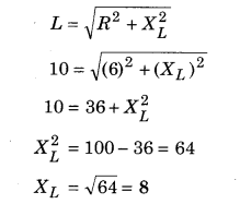
The ohmic resistance of a coil is 6 Ω. If impedance of the coil is 10 Ω, then find inductive reactance (XL ) of the coil.
Answer:
Ohmic resistance (R) = 6 Ω
Impedance of coil (Z) = 10 Q
For inductor and resistance circuit
Question 6.
Write phase difference between current and voltage for an ac circuit, when (i) f = fr, (ii) f < fr (iii) f > fr Here fr is the resonant frequency.
Answer:
(i) f = fr when XL = XC
The circuit is purely resistive i.e., it is non-inductive. Therefore, current and voltage in the circuit are in the same phase.
(ii) f < fr as XL = ωL = 2πfL and XC = \(\frac{1}{\omega C}=\frac{1}{2 \pi f C}\)
∴ When f is small, XL is small, XC is large. The circuit is capacitance dominated. Therefore, current in the circuit leads the voltage by phase angle ϕ.
(iii) f > fr
So, XL becomes large and XC becomes small. The circuit is inductance dominated. The current lags behind the voltage by phase angle ϕ.
Question 7.
What is bandwidth? Write its value in LCR circuit.
Answer:
Bandwidth of the system is the range of frequencies for which the total power is more than the half of maximum power. It is represented of Δf.
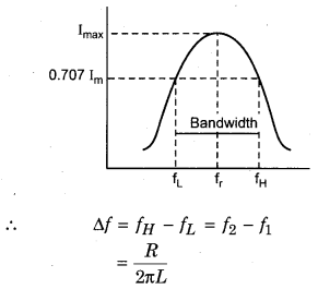
Question 8.
What are half power point frequencies? What is value of current at there frequencies?
Answer:
Bandwidth of the system is the range of frequencies for which the total power is more than the half of maximum power. It is represented of Δf.
Question 9.
What will be power factor when resistance and reactance of a coil are equal?
Answer:
Power factor in circuit
cosϕ = \(\frac{R}{Z}\)
When R = Z
∴ cos ϕ = \(\frac{R}{Z}\) = 1
Question 10.
In electric power transmission circuits the meaning of low power factor is more power decay. Explain.
Answer:
We know that power loss
P = Irms Vrms cosϕ,
Small value of ϕ i. e., cos ϕ = more
∴ Power loss is more.
Question 11.
What will be value of impedance, frequency and power factor for a resonant LCR circuit? Write the expression.
Answer:
In L-C-R circuit :
At the condition of resonance
Z = R
Impedance = Resistance
Frequency = not changed R
Power factor cos ϕ = \(\frac{R}{Z}\) = 1
Question 12.
On what principle does transformer works? Write its uses.
Answer:
Transformer works on the principle of mutual induction and it is use to convert the high voltage to low voltage or low voltage to high voltage.
Question 13.
Find out the average value of current during first half cycle of an alternating current.
Answer:
Average or Mean Value of Alternating Current and Voltage
We know that the average value of a.c. over complete cycle is zero, so to impart some meaning to the average value of A.C., we find out its average over the half cycle only.
Average Value of A.C. : It is defined as that value of steady current (d.c.) which sends the same amount of charge through the circuit in a time equal to that sent by a.c. in half the time period. It is denoted by
I = Im sin ωt
Assuming that this current remains constant for a small time dt, then charge dq flowing the circuit in the small time dt is given by
dq = i dt = Im sin ωt dt
If total charge q flows through the circuit in time T/2, then
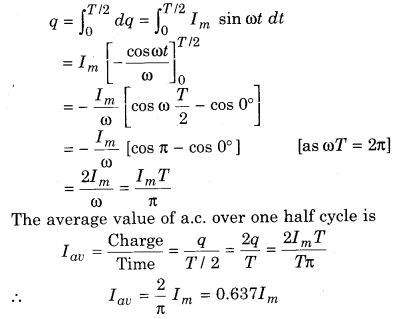
Hence, the mean value or average value of a.c. over one half cycle is 0.637 times its peak value.
Similarly, it can be proved,, that average alternating emf over one half cycle is
Vav = \(\frac{2}{\pi}\) Vm = 0.637Vm
Question 14.
What are the causes of energy loss in a transformer? How can we minimise them?
Answer:
Most of the transformer have efficiency of 90-99%. This means the wastage of the power is negligible. The above analysis was for an ideal transformer. In a real transformer the energy losses are due to various reasons as detailed below.
- Leakage of magnetic flux : Due to the air gaps in the core the amount of magnetic flux linked with the secondary is less than that of the primary as the energy is lost. It can be reduced by winding the primary and secondary coils over one another.
- Iron loss : This is the energy lost as heat due to induced eddy currents in the iron core (alternating magnetic flux induces these currents). This loss is also called the eddy current loss. This is reduced by making core of laminated sheets of soft iron insulated from each other.
- Copper loss : It is the heat energy lost across the resistance of copper windings used in primary and secondary coils. This loss can be minimised by using thick copper wire for the primary and secondary windings.
- Hysteresis loss : This loss is due to heating up of core due to its repeated cycles of magnetisation and demagnetisation when an alternating emf is applied across the primary. This loss can be minimised by selecting a core material having a narrow hysteresis loop.
- Magnetostriction : It is the loss due to the humming sound produced in the transformer.
Question 15.
Find out phase difference between current and voltage in a series R-L circuit and derive its relation for impedance of the circuit.
Answer:
Voltage Applied to a Capacitor
Let a source of alternating emf be connected across a capacitor. The instantaneous value of alternating emf is given by
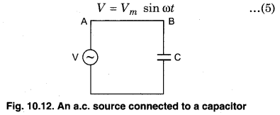
When a d.c. source is connected across a capacitor the current flows across it for a short time interval till the capacitor is charged. As the charges start accumulating on the capacitor plates a potential difference across them also increases which opposes the current. This phenomenon continues till the potential difference across the plates becomes equal to the potential difference across the terminals of the battery. As this happens the charging of the capacitor stops and the current in the circuit falls to zero.
When capacitor is connected to a source of alternating emf as shown in figure. (10.12), the capacitor gets charged for first half cycle in one direction and then gets discharged. It again gets charged for the second half cycle but now in the opposite direction and again gets discharged and so on. Thus, a capacitor connected across an a.c. source limits the current but not completely stop the flow of charge. Thus, there is a continuous alternating current in the circuit. If q is charge on the capacitor at any instant t.
Let I be the instantaneous current flowing through the capacitor, then
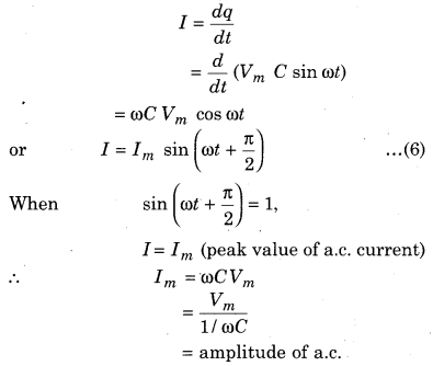
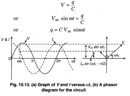
Comparing equations (5) and (6), it is clear that in a capacitive a.c. circuit, current leads the voltage by nl 2. This is shown in figure (10.13 a) and the corresponding phasor diagram is shown in figure (10.13b).
As is clear from the figure that the current phasor I is π / 2 ahead of voltage phasor V. When these phasors are rotated counter clockwise, they generate the curves given in figure. (10.13). Comparing equation Im = \(\frac{V_{m}}{1 / \omega C}\) with Ohm’s law, we find out that the quantity \(\frac{1}{\omega C}\) plays the same role in this circuit as is done by the resistance in the purely resistive circuit thus, it is the effective reactance offered by the capacitor C and is called capacitive reactance. It is denoted by XC .
Thus, XC = \(\frac{1}{\omega C}=\frac{1}{2 \pi f C}\) ……………… (7)
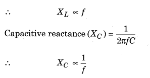
where f is the frequency of the a.c. supply. As is clear from equation (7) that unlike inductive reactance, capacitive reactance decreases with an increase in the frequency of a.c. It is also measured in ohms (Ω).
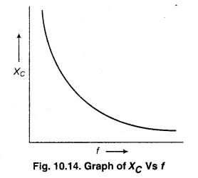
In a d.c. circuit f = 0, thus XC = ∞. Thus, a capacitor offers infinite resistance to d.c. current.
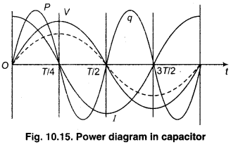
As charge q = CV
∴ Power in circuit P = VI
Voltage, current, charge and power are plotted in figure as shown below.
RBSE Class 12 Physics Chapter 10 Long Answer Type Questions
Question 1.
A pure inductance is connected through alternating voltage circuit. Find out the value of current, phase difference, reactance and average consumed energy rate in the circuit. Draw phasor diagram also.
Answer:
A.C. Voltage Applied on an Inductor
Let a source of alternating emf be connected across a inductor. The instantaneous value of alternating emf is given by
V = Vm sin ωt …………….. (1)
Here we have assumed that this inductor has negligible resistance though practically its windings have appreciable resistance.
If I is the instantaneous current through L at any time t, then self-induced Faraday emf in the inductor is
ε = \(-\frac{L d I}{d t}\)
Here L is the self inductance of the inductor and the -ve sign shows that induced emf opposes the applied emf (Lenz’s law).
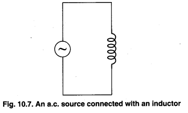
The applied voltage V must be equal and opposite to the induced voltage ε to maintain the flow of current in the circuit.
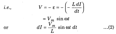
This equation tells us that the current as a function of time, must be such that the quantity \(\frac{d I}{d t}\) (slope) is a sinusoidally varying quantity, having an amplitude \(\frac{V_{m}}{L}\)and in phase with the source voltage.
The total current flow in the circuit, equation 2 is integrate both the sides
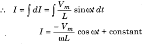
The integration constant here has dimensions of current and does not depend on time. As the source has an emf oscillating symmetrically about zero, the current it sustains should also oscillate symmetrically about zero, so constant exists. Hence, the integration constant is zero.
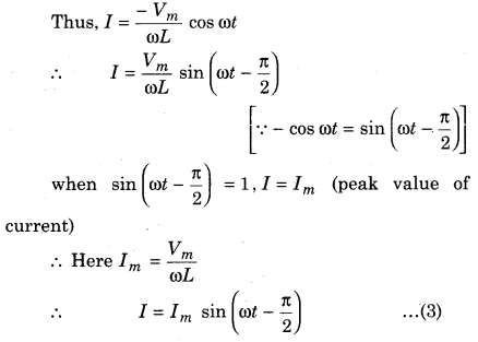
Comparing equations (1) and (2), it is clear that in an a.c. circuit containing inductance only, current lags behind the voltage by a phase angle of π/ 2 or one-quarter (1/ 4) cycle. This is shown in figure (10.8 a) and the corresponding phasor diagram is shown in figure. (10.8 b)
As it is clear from the figure that current phasor I is \(\frac{\pi}{2}\) behind the voltage phasor V. When these phasors are rotated in the counter-clockwise direction, they generate the curves given in figure (10.8 a) and by
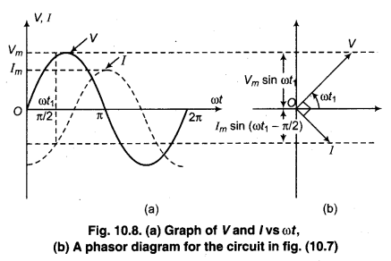
equations (1) and (3). Comparing equation Im = \(\frac{V_{m}}{\omega L}\) with Ohm’s law, we find out that the quantity ωL plays the same role here in the circuit as is done by the resistance in the purely resistive circuit. Thus, it is the effective resistance offered by the inductance L and is called inductive reactance. It is denoted by XL.
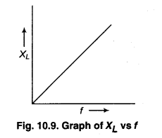
Thus, XL = ωL = 2πfL …………… (4)
Where f is the frequency of the a.c. supply. It is obvious from equation (4) that inductive reactance is not constant but increases with increase in the frequency of the a.c. supply. In a d.c. circuit, f = 0 and as such XL = 0, thus a pure inductance offers zero resistance in a d.c. circuit. The inductive reactance is measured in ohms (ω).
Question 2.
An alternating voltage is connected to an R-L circuit. Derive a relation for impedance and current. Draw phasor diagram also.
Answer:
Voltage Applied to a Capacitor
Let a source of alternating emf be connected across a capacitor. The instantaneous value of alternating emf is given by
When a d.c. source is connected across a capacitor the current flows across it for a short time interval till the capacitor is charged. As the charges start accumulating on the capacitor plates a potential difference across them also increases which opposes the current. This phenomenon continues till the potential difference across the plates becomes equal to the potential difference across the terminals of the battery. As this happens the charging of the capacitor stops and the current in the circuit falls to zero.
When capacitor is connected to a source of alternating emf as shown in figure. (10.12), the capacitor gets charged for first half cycle in one direction and then gets discharged. It again gets charged for the second half cycle but now in the opposite direction and again gets discharged and so on. Thus, a capacitor connected across an a.c. source limits the current but not completely stop the flow of charge. Thus, there is a continuous alternating current in the circuit. If q is charge on the capacitor at any instant t.
Let I be the instantaneous current flowing through the capacitor, then
Comparing equations (5) and (6), it is clear that in a capacitive a.c. circuit, current leads the voltage by nl 2. This is shown in figure (10.13 a) and the corresponding phasor diagram is shown in figure (10.13b).
As is clear from the figure that the current phasor I is π / 2 ahead of voltage phasor V. When these phasors are rotated counter clockwise, they generate the curves given in figure. (10.13). Comparing equation Im = \(\frac{V_{m}}{1 / \omega C}\) with Ohm’s law, we find out that the quantity \(\frac{1}{\omega C}\) plays the same role in this circuit as is done by the resistance in the purely resistive circuit thus, it is the effective reactance offered by the capacitor C and is called capacitive reactance. It is denoted by XC .
Thus, XC = \(\frac{1}{\omega C}=\frac{1}{2 \pi f C}\) ……………… (7)
where f is the frequency of the a.c. supply. As is clear from equation (7) that unlike inductive reactance, capacitive reactance decreases with an increase in the frequency of a.c. It is also measured in ohms (Ω).
In a d.c. circuit f = 0, thus XC = ∞. Thus, a capacitor offers infinite resistance to d.c. current.
As charge q = CV
∴ Power in circuit P = VI
Voltage, current, charge and power are plotted in figure as shown below.
Question 3.
What do you mean by resonant circuit? Write necessary condition for series resonant LCR circuit. Derive a relation of frequency. What are the uses of this circuit?
Answer:
Series L-C-R Resonance Circuit
A series LCR circuit is said to be resonance when the current has its maximum value. Before deriving let us understand the meaning of few terms.
Resonance is quite a common phenomenon in the system which have a tendency to oscillate at a particular frequency known as the natural frequency of the system. Now, if such a system is driven by an energy’ source at a frequency close to the natural frequency of the system, the amplitude of oscillations becomes high and this condition is termed as resonance.
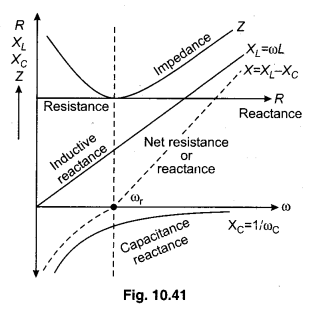
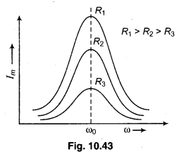
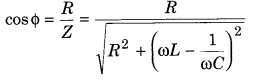
A very common example is that of child swinging back and forth at a natural frequency. Now, if by pushing the swing at regular intervals such that the frequency of pushes is close to that of the swing makes the amplitude of swing very large. The impedance for an LCR circuit is given by the formula.
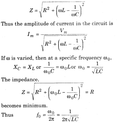
The frequency f0 of the applied voltage for which the current in a LCR series circuit becomes maximum is called the resonant frequency.
The current amplitude at resonant frequency is
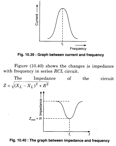
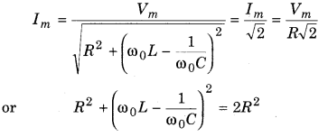
Resonance Curve : In the condition of resonance, XL = XC, then current flowing in the circuit, I is maximum and the frequency at which this condition is meet, is called resonance frequency fr.
If XL ≠ XC then (XL – XC) ≠ 0
Thus, (XL – XC)2 > 0
and Z > R
Thus, the value of current I = V/Z will be less than the resonant current. Figure (10.39) shows the changes in current due to frequency. This is called resonance curve.
Resonance circuits have wide variety of applications as in tuning system of radio or of a TV set. The antenna accepts signals form various broad casting stations which act as a source in the tuning circuit of the radio. Thus the circuit can be driven by many frequencies. To tune a one particular radio station, the capacitance of the capacitor in the tunning circuit is varied. By doing so, the resonant frequency of the circuit becomes nearly equal to the frequency of the received radio signal. At this point the current amplitude corresponding to the frequency of the signal of the particular radio station in the circuit is maximum and is received on the set. The series resonant circuit is also known as acceptor circuit, because out of the number of frequency feed to it, it accepts only one frequency and rejects the rest.
Remember : The resonance phenomenon occurs in a circuit only if L and C are both part of it as the voltage across L and C are out of phase they cancel out each other and the current amplitude becomes Im = Vm / R. This means that RL or RC circuit cannot exhibit resonance.
Question 4.
Draw a graph between frequency and current for a series LCR circuit. Represent half power frequencies on the graph and derive a relation for bandwidth.
Answer:
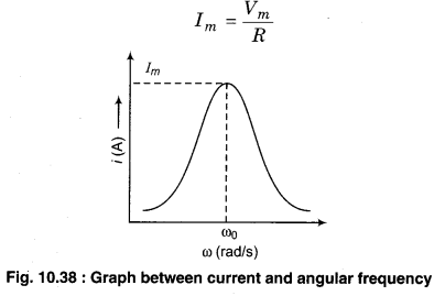
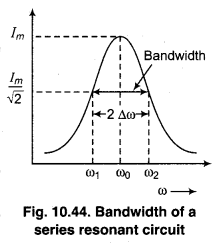
Band Width
The figure (10.43) shows the variation of current amplitude Im in a series LCR circuit with angular frequency value of R. The current amplitude Im in a series LCR circuit is given by
Im = \(\frac{V_{m}}{\sqrt{R^{2}+\left(\omega L-\frac{1}{\omega C}\right)^{2}}}\)
The current amplitude has a peak value at the resonant frequency that is when ω = ω0 = \(\frac{1}{\sqrt{L C}}\) other value of to, the value of current is less than the maximum value. As is clear from the figure that as the resistance in the circuit is reduced, the resonance curve becomes sharper. The more quickly the current amplitude (Im) falls for changes of frequency on both sides of resonant frequency (ω0), the sharper is said to be resonance. The sharpness of resonance of a circuit is described by its quality factor, Q also known as Q-factor.
It is defined as the ratio of the series resonant frequency to the difference taken between the two frequencies on both sides of resonant frequency such that at each of these frequencies, the current amplitude is 1/2 times its maximum value.
Mathematically it is given by
Q = \(\frac{\omega_{0}}{\omega_{1}-\omega_{2}}=\frac{\omega_{0}}{2 \Delta \omega}\)
The difference ω1 – ω2 = 2Δω is termed as the bandwidth of the circuit.
The smaller the value of Δω , the sharper is the resonance.
here, ω1 = ω0 + Δω
and ω2 = ω0 – Δω
Thus ω1 – ω2 = 2Δω
Q is a dimensionless quantity.
Let us now derive the expression for the Q-factor.
At Δ = ω1 and ω2

Question 5.
Establish a relation for power in an alternating current circuit. What will be effect in formula, when there is no any reactance and resistance in the circuit? Define power factor.
Answer:
Average Power in A.C. Circuit
The power of a circuit is defined as rate of energy transfer between the flowing charge and the circuit. In dc circuits, power is given by the product of voltage and current.
However in an ac circuit both voltage and current keep on varying with time. Thus for an ac circuit, the instantaneous power is the product of the instantaneous voltage and instantaneous current.
For an ac circuit the voltage and current at any instant is given by
V = Vm sinωt
I = Im sin(ωt + ϕ)
when ϕ is phase between the voltage and the current
∴ The instantaneous power is given by
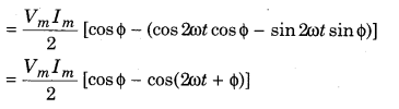
P = VI = Vm sinωt × [Im sin(ωt + ϕ)]
= VmIm sinωt [sinωt cosϕ> + cosωt sinϕ]
= VmIm [sin2 ωt cosϕ + sin 2ωt cos cot sinϕ]
= \(\frac{V_{m} I_{m}}{2}\) [(1 – cos2ωt) cosϕ + sin2ωt sinϕ]
If the instantaneous power is assumed to remain constant for a small time dt then find out the work done during this time,
dW = pdt
∴ Work done over a complete cycle
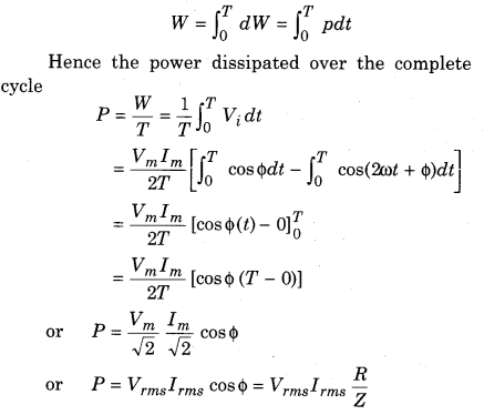
Thus the average power dissipated depends upon the voltage current and cosine of the phase angle between them.
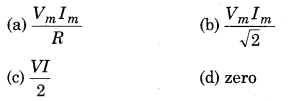
1. Resistive circuit: If the circuit contains only pure R, voltage and current are in same phase i.e., ϕ = 0 or cosϕ= 1. The power dissipated is maximum.
P = Vrms Irms = \(\frac{V_{r m s}^{2}}{R}\)
2. Pure inductive circuit : If the circuit contains only an inductor, then the voltage leads the current in phase by \(\frac{\pi}{2}\) i.e., ϕ = \(\frac{\pi}{2}\)
∴ cos ϕ = 0
P = Vrms Irms\(\cos \frac{\pi}{2}\) = 0
∴ No power is dissipated even though a current is flowing in the circuit.
3. Purely capacitive circuit : If the circuit contains only a capacitor, then the current leads the voltage by \(\frac{\pi}{2}\) i.e., ϕ = \(\frac{\pi}{2}\) or cosϕ = 0
∴ P = Vrms Irms\(\cos \frac{\pi}{2}\) = 0
Thus the average power consumed over a complete cycle is zero here.
4. LCR series circuit : The power dissipated is given by P = Vrms Irms cos ϕ where ϕ = \(\tan ^{-1} \frac{X_{L}-X_{C}}{R}\)
So, ϕ may have non-zero values in a LR, CR or LCR circuit. Even then the power is dissipated only across the resistor.
5. Power dissipated at resonance in LCR circuit : At resonance XC – XL = 0 and ϕ = 0.
Thus cosϕ = 1 and P = I2Z = I2R. Thus the power dissipated is maximum (through R) at resonance.
Power Factor
The average power for an ac circuit is given by
P = Vrms Irmscos ϕ
Vrms Irms is called the apparent or virtual power,
P is called the true power.
cos ϕ is called the power factor of an ac circuit.
∴ True power = Apparent power × Power factor
Thus the power factor is defined as the ratio of
the true power and apparent power for an ac circuit.
Let us calculate its value for different cases.
1. Purely resistive circuit, ϕ = 0°.
∴ Power factor = 1 (= maximum value)
2. Purely inductive circuit, ϕ = 90°.
∴ Power factor = cos 90° = 0 (minimum value)
3. Purely capacitive circuit ϕ = 90°.
∴ Power factor = cos 90° = 0 (minimum)
4. For a series LCR circuit, the power factor is
From the above discussion it becomes clear that the power dissipated in a circuit depends upon the power factor. Larger the value of power factor, greater is the power dissipated.
RBSE Class 12 Physics Chapter 10 Numerical Questions
Question 1.
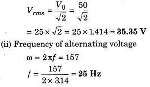
Alternating voltage in any alternating current circuit is V = 50 sin (157t + ϕ) V, then find out the :
(i) root mean square value of alternating voltage.
(ii) frequency of the alternating voltage.
Solution:
Given V = 50sin (157t + ϕ)
Compare V = Vm (sin ωt + ϕ)
∴ Vm = 50 volt and to = 157 rad/sec
(i) Root mean square value of voltage
Question 2.
At which time, sinusoidal alternating current will be
(i) \(\frac{1}{2}\) time
(ii) \(\frac{\sqrt{3}}{2}\) time of its peak value.
Solution:
The instantaneous value of current is
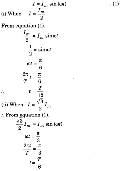
Question 3.
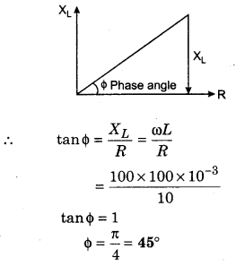
A resistance of 10 Ω and a inductance of 100 mH are connected in series through an alternating voltage source V = 100 cos ωt. Find out phase difference between current and voltage for the circuit.
Solution:
Given R) = 10 Ω and Inductance (L) = 100 mH
Voltage source = 100cos (100t) and compare by the relation
V = V0 cos (ωt)
V0 = 100V
ω = 100 rad/s
Question 4.
Find out the inductive reactance for 100 mH inductance connected through alternating current of 1 kHz frequency. If voltage of the source is 6.28 V, then find out current in the inductance.
Solution:
Frequency of a.c. current f = 1 kHz
= 1 × 10³ Hz
Coefficient of self induction (L) = 100 mH
= 100 × 10-3H
Potential of source (V) = 6.28 V
Inductive reactance (XL) = 2πfL
= 2 × 3.14 × 1 × 103 × 100 × 10-3
= 6.28 × 100
= 628 Ω
Current in inductor (I) = \(\frac{V}{X_{L}}=\frac{6.28}{628}\)
= \(\frac{1}{100}\) = 0.01A
Question 5.
The inductance of the coil is 1 H.
(i) At which frequency will its reactance be 3140 Ω ?
(ii) What will be the capacity of the capacitor so that its reactance remain same at the same frequency?
Solution:
Inductance (L) = 1 H
Inductive reactance (XL = 2πfL)
3140 = 2 × 3.14 × f × 1
Question 6.
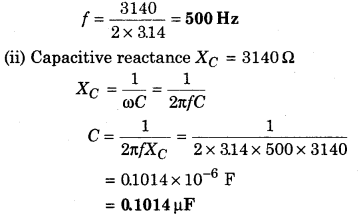
A condenser of 120 µF is connected through an ac source of frequency 50 Hz. Calculate its capacitive reactance. If frequency changes to 5 MHz, then what will be effect on reactance?
Solution:
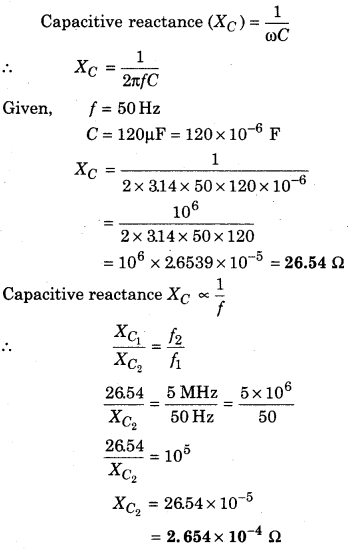
Question 7.
The resistance of a coil is R = 10 Ω and inductance is L = 0.4 H. It is connected to an ac source of 6.5 V, \(\frac{30}{\pi}\) Hz. Find out the average n power consumed in the circuit.
Solution:
Resistance of coil (R) = 10 Ω
Inductor (L) = 0.4 H
Source of potential (V) = 6.5 V
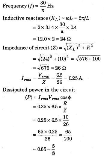
Question 8.
A bulb of 60 V, 10 W is connected to an ac source. An inductance is connected in series with it. If bulb is illuminated with full intensity, then find out the value of inductance of the coil. (f = 60 Hz)
Solution:
Marked voltage on bulb (V) = 60 V
ower of bulb (P) = 10 W
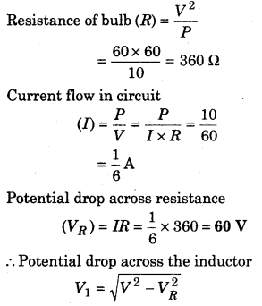
Question 9.
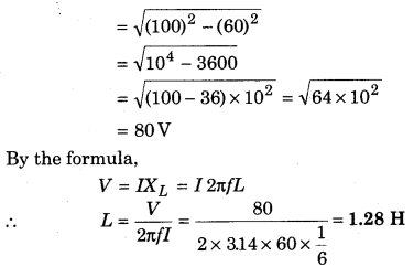
An alternating source of Vrms = 120 V, f = 60 Hz is connected to an series circuit containing L = 200 mH, C = 40 µF and R = 20 Ω. Determine :
(i) total reactance
(ii) impedance
(iii) power factor
(iv) average power.
Solution:
Voltage (Vrms) = 120 V
and frequency (f) = 60 Hz
Inductance (L) = 200 mH = 200 × 10-3 H
Capacitance (C) = 40 µF = 40 × 10-6F
Resistance (R) = 20 Ω
Inductive reactance (XL) = ωL = 2πfL
= 2 × 3.14 × 60 × 200 × 10-3
= 75.36 Ω
= \(\frac{120}{21.93}\) × 120 × 0.912
= 598.850 W
Question 10.
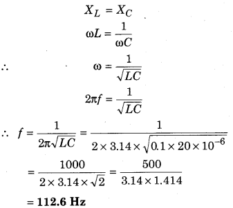
An inductance, a capacitance and a resistance are in series. If L = 0.1 H, C = 20 µF, R = 10Ω, then at which frequency, the circuit will be in resonance?
Solution:
Inductance of circuit (L) = 0.1 H
Capacitance (C) = 20µF = 20 × 10-6 F
Resistance (R) = 10 Ω
At the condition of resonance :
Question 11.
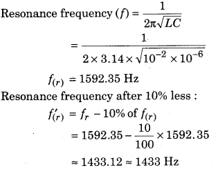
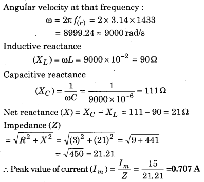
In a LCR circuit, an inductance of 10 mH, a resistance of 3 Ω, and a capacitor of 1 µF are connected in series through an ac source 15 cosωt V. At the frequency less than 10% of resonant frequency, find out the peak value of current.
Solution:
Inductance (L) = 10 mH = 10 × 10-3 H
Resistance (R) = 3 Ω
Capacitance (C) = 1 µF = 10-6 F
Source of potential (V) = 15 cos ωt V and compare by the relation
V = Vm cosωt
Vm = 15V
Question 12.
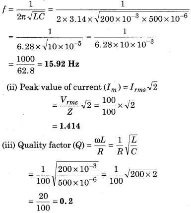
An inductor L = 200 mH, a capacitor C = 500 µ.F and a resistance R = 100 Ω are connected in series through an ac source of 100 V. Determine :
(i) frequency at which the power factor of the circuit is 1.
(ii) peak value of current at this frequency
(iii) quality factor.
Solution:
Inductance (L) = 200mH = 200 × 10-3 H
Capacitance (C) = 500µF = 500 × 10-6 F
Resistance (R) = 100 Ω
Potential of source (V) = 100 V
(i) Power factor is unit then :
Question 13.
Power factor of a coil is 0.707 at frequency 60 Hz. If frequency changes to 120 Hz, then what will be the power factor?
Solution:
Power factor of coil (cos ϕ) = 0.707
Frequency (f1) = 60Hz
Frequency (f2) = 120Hz
By the formula,
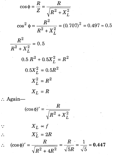
Question 14.
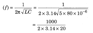
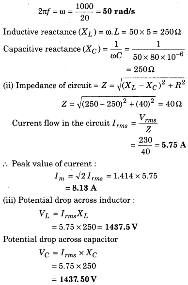
A series LCR circuit connected through an alternating voltage 230 V. If L = 5 H, C = 80 µF, R = 40 Ω, then find out the :
(i) resonant frequency
(ii) impedance of the circuit and peak value of current at resonant frequency.
(iii) square mean root value of voltages at three components.
Solution:
Alternating voltage (V) = 230 V
Inductance (L) = 5H
Capacitance (C) = 80 µF = 80 × 10-6 F
Resistance (R) = 40 Ω
(i) Resonance frequency
Question 15.
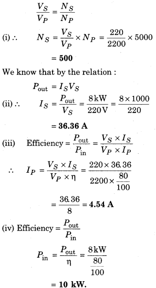
A step down transformer changes the voltage from 2200 V to 220 V. Its primary coil has 5000 turns. If the efficiency of the transformer is 80% and output power is 8 kW, then find out the:
(i) NS
(ii) IS
(iii) IP
(iv) input power.
Solution:
Potential in primary coil (VP)= 2200 V
Potential in secondary coil (VS) = 220 V
Turns in primary coil (NP)= 5000
Efficiency (η) = 80%
Output power Pout = 8 kW
By the formula :