Rajasthan Board RBSE Class 12 Physics Chapter 12 Nature of Light
RBSE Class 12 Physics Chapter 12 Text Book Exercise with Answers
RBSE Class 12 Physics Chapter 12 Multiple Choice Type Questions
Question 1.
To show the phenomenon of interference we need two sources which emit radiation :
(a) of equal frequency and fixed phase difference
(b) of nearly equal frequency
(c) of equal frequency
(d) of different wavelength
Answer:
(a) of equal frequency and fixed phase difference
When two light waves of the equal frequency and have a fixed phase difference then phenomenon of interference occurs.
Question 2.
In Young’s double slit experiment monochromatic light source is used. The shape of the fringes on the screen will be :
(a) straight line
(b) hyperbola
(c) parabola
(d) circle
Answer:
(b) hyperbola
Fringes are hyperbolic in shape.
Question 3.
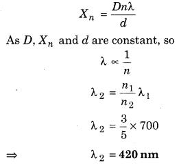
In an interference experiment on using light of wavelength 700 nm, third bright fringe received at a point on the screen. At the same point to receive fifth bright fringe the wavelength of light is :
(a) 210 nm
(b) 315 nm
(c) 420 nm
(d) 490 nm
Answer:
(c) 420 nm
Given, λ1 = 700 nm = 700 × 10-9 m = 7 × 10⁻⁷ m
n1 = 3, λ2 = ?, n2 = 5 (bright), X3 = X5
Distance of nth bright fringe from central bright fringe
Question 4.
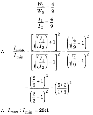
In Young’s double slit experiment if the ratio of the widths of slits are 4 : 9, then the ratio of maximum and minimum frequencies will be :
(a) 196 : 25
(b) 81 : 16
(c) 25 : 1
(d) 9 : 4
Answer:
(c) 25 : 1
If widths of slits are W1 and W2, then
Question 5.
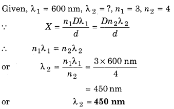
In Young’s double slit experiment, light of two different wavelengths are used. For yellow orange colour (λ = 600 nm) third order bright fringe position coincide with fourth order bright fringe of second colour. The wavelength of second colour will be :
(a) 500 nm
(b) 450 nm
(c) 225 nm
(d) 350 nm
Answer:
(b) 450 nm
Question 6.
In Young’s double slit experiment the maximum intensity of light is Imax, then the intensity of light of the path difference \(\frac{\lambda}{2}\) will be
![]()
Answer:
(d)
At path difference \(\frac{\lambda}{2}\), destructive interference will occur. So intensity will be Imin
Let I1 = I2 = I0
∴ Imax = I1 + I2 + \(2 \sqrt{I_{1} I_{2}}\) = I0 + Io + 2I0 = 4I0
and Imin = I1+ I2 \(\sqrt{I_{1} I_{2}}\) = I0 + Io – 2I0 = 0
Question 7.
Choose the correct statement:
In most of the circumstances, the diffraction of sound is more possible compare to diffraction of light:
(a) Medium is necessary for sound propagation
(b) Sound waves are longitudinal while light rays are transverse
(c) Wavelength of light is very less comparable to wavelength of sound
(d) Speed of sound wave order is less than 6 compare to speed of light
Answer:
(b) Sound waves are longitudinal while light rays are transverse
Diffraction effect is more pronounced if the size of obstacle or aperture is of the order of the wavelength of the waves. As the wavelength of light (~ 10-6 m) is much smaller than the size of the objects around us, so diffraction of light is not easily seen. But sound waves have large wavelength. They get easily diffracted by the objects around us.
Question 8.
According to given figure, in an experiment, electrons are passed through de-Broglie wavelength order towards a narrow’ slit of width d and they are detected at D distance on a screen. The intensity distribution will be:
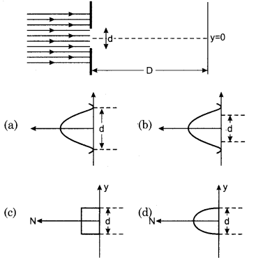
Answer:
(b)
Diffraction pattern must be broader than width of the slit.
Question 9.
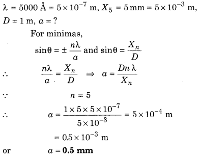
A light of 5000 A wavelength is diffracted by a single slit. In diffraction pattern fifth minima formed at 5 mm distance from central maxima. If distance between screen and slit is lm, then the width of the slit will be :
(a) 0.1 mm
(b) 0.3 mm
(c) 0.5 mm
(d) 0.8 mm
Answer:
(c) 0.5 mm
Question 10.
A beam of microwaves whose wavelength is 0.052 m is coming towards a rectangular aperture of width 0.35 m. Resultant diffraction pattern is observing on a wall at 8.0 m distance from aperture. The distance between first and second order outer fringes will be :
(a) 1.3 m
(b) 1.8 m
(c) 1.19 m
(d) 2.5 m
Answer:
(c) 1.19 m
λ = 0.052 m, α = 0.36 m, D = 80 m
If first maxima is at distance X, from central maxima, then
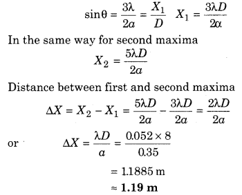
Question 11.
The aperture of astronomical telescope is large because:
(a) to remove spherical defect
(b) for high limit of resolution
(c) to enlarge observation area
(d) for less dispersion
Answer:
(a) to remove spherical defect
The aperture of astronomical telescope is large to remove spherical aberration.
Question 12.
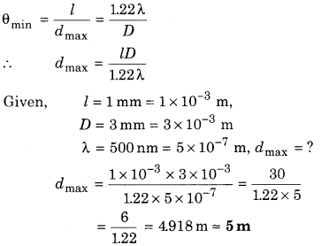
Two white points are placed on a black paper at 1 mm distance. They are seen by an eye of cornea diameter 3 mm. What will be the maximum distance between them, so they are exactly resolved by eye (wavelength of light = 500 nm)?
(a) 6 m
(b) 3 m
(c) 5 m
(d) 1 m
Answer:
(c) 5 m
Question 13.
Electromagnetic waves are transverse. Evidence of this is given by :
(a) polarisation
(b) interference
(c) reflection
(d) diffraction
Answer:
(a) polarisation
Polarisation is the proof of transverse nature of light waves.
Question 14.
For reflection from air to glass, the value of incident angle for which the reflected light is totally polarised (refractive index = n):
(a) \(\tan ^{-1}\left(\frac{1}{n}\right)\)
(b) \(\sin ^{-1}\left(\frac{1}{n}\right)\)
(c) sin-1(n)
(d) tan-1(n)
Answer:
(d) tan-1(n)
From Brewster’s law
n = tan ip ⇒ tan-1(n)
Question 15.
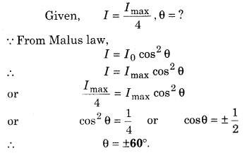
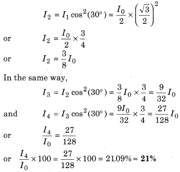
Four polaroids are so placed that the transmission axis of each is inclined at an angle of 30° from the axis of the previous polaroid in the same direction. If unpolarised light beam falls on the first polaroid, then what will be the intensity of light emerging from each polaroid?
(a) 10%
(b) 21%
(c) 50%
(d) 2%
Answer:
(b) 21%
Emerging out intensity from first sheet
I0 = \(\frac{I_{0}}{2}\)
Emerging out intensity from second sheet
Question 16.
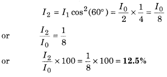
Two nicols are so oriented that the angle between their major axis is 60°, then the percentage of emerging out light from the system will be :
(a) 30%
(b) 100%
(c) 12.5%
(d) 37.5%
Answer:
(c) 12.5%
Intensity of emerging out light from first Nicol prism
I0 = \(\frac{I_{0}}{2}\)
Intensity of emerging out light from second Nicol
RBSE Class 12 Physics Chapter 12 Very Short Answer Type Questions
Question 1.
Whose direction is given by the line perpendicular to wavefront?
Answer:
Direction of ray.
Question 2.
On which physical quantities do the Young’s fringe width depend?
Answer:
Fringe width, β = \(\frac{D \lambda}{d}\)
So, β depends on : (i) Wavelength λ, (ii) Distance of slit from screen D, (iii) Distance between slits 2d.
Question 3.
Write statement of Huygen’s principle of diffraction.
Answer:
According to Fresnel, diffraction is the result of superposition of secondary waves starting from different parts of the same wavefront.
Question 4.
What type of wavefront will emerge :
(i) from a point source?
(ii) from a far light source?
Answer:
(i) Spherical wavefront
(ii) Plane wavefront.
Question 5.
What is the most important condition for interference by two waves?
Answer:
Both sources of light should be coherent.
Question 6.
In single slit experiment how does angular separation change when the distance between slit and screen becomes two times?
Answer:
Angular separation θ ∝ \(\frac{1}{D}\), when D becomes twice, then θ remains half.
Question 7.
What should be the order of the aperture or obstacle to observe diffraction with it?
Answer:
Of the order of the wavelength.
Question 8.
Name two physical phenomena which illustrate wave nature of light.
Answer:
Interference and polarisation.
Question 9.
Despite the wave nature of light why does it seem to move in straight line.
Answer:
Because wavelength of light is very small.
Question 10.
In single slit diffraction, which type of light wave undergo superimpose?
Answer:
Slit becomes source of secondary wavelets. These wavelets spread out in all directions, thus causing diffraction of light.
Question 11.
What is mathematical form of Malus law?
Answer:
According to Malus I = I0 cos2 θ
Here I0 is the maximum intensity of transmitted light, θ is the angle between planes of polariser and analyser.
RBSE Class 12 Physics Chapter 12 Short Answer Type Questions
Question 1.
Describe Huygens’ principle for light waves.
Answer:
Huygens Wave Theory and Wavefront
We would first define a wavefront : When we drop a small stone on a calm pool of water, waves spread out from the point of impact. Every point on the surface starts oscillating with time. At any instant, a photograph of the surface would show circular rings on which the disturbance is maximum. Clearly, all points in such a circle are oscillating in phase because they are at the same distance from the source. Such a locus of points, which oscillate in phase is called a wavefront, thus a wavefront is defined as a surface of constant phase. The speed with which the wavefront waves outwards from the source is called the speed of the wave. The energy of the wave travels in a direction perpendicular to the wavefront.
The geometrical shape of a wavefront depends upon the source of the disturbance. Some of the common shapes are :
1. Spherical Wavefront : In the case of waves travelling in all directions from a point source, the wavefronts are spherical in shape. This is because all such points which are equidistant from the point source will lie on a sphere (figure 12.1 (a)) and the disturbance starting from the source S will reach all these points simultaneosly.
2. Cylindrical Wavefront : When the source of light is linear in shape, such as a fine rectangular slit, the wavefront is cylindrical in shape. This is because the locus of all such points which are equidistant from the linear source will be a cylinder. Figure 12.1 (b).
3. Plane Wavefront : As a spherical or cylindrical wavefront advances, its curvature decreases progressively. So a small portion of such a wavefront at a large distance from the source will be a plane wavefront. Figure 12.1 (c).
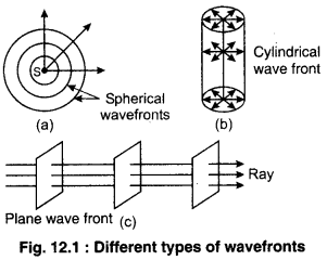
It is seen that whatever is the shape of a wavefront, the disturbance travels along straight lines emerging from the source, i.e., the energy of a wave travels in a direction perpendicular to the wavefront. An arrow drawn perpendicular to a wavefront in the direction of propagation of a wave is called a ray.
Now, if we know the shape of the wavefront at t = 0, then Huygens principle allows us to determine the shape of the wavefront at a later time τ. Thus, Huygens principle is essentially a geometrical construction, which gives the shape of the wavefront at any time allows us to determine the shape of the wavefront at a later time. Let us consider a diverging wave and let F1F2 represent a portion of the spherical wavefront at t = 0 [figure 12.2 (a)]. Now, according to Huygens principle, each point of the wavefront is the source of a secondary disturbance and the wavelengths emanating from these points spread out in all directions with the speed of the wave. These wavelets emanating from the wavefront are usually referred to as secondary wavelets and if we draw a common tangent to all these spheres, we obtain the new position of the wavefront at a later time.
Thus, if we wish to determine the shape of the wavefront at t = τ, we draw spheres of radius ox from each point on the spherical wavefront where v represents the speed of the waves in the medium. If we now draw a common tangent to all these spheres, we obtain the new position of the wavefront at t = τ. The new wavefront shown as G1G2 in figure 12.2 (a) is again spherical with point O as the centre.
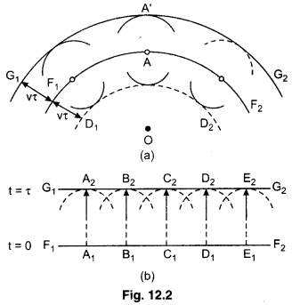
The above model has one shortcoming, we also have a backwave which is shown as D1D2 in figure 12.2(a). Huygens argued that the amplitude of the secondary wavelets is maximum in the forward direction and zero in the backward direction; by making this adhoc assumption, Huygens could explain the absence of the backwave. However, this adhoc assumption is not satisfactory and the absence of the backwave is really justified from more rigorous wave theory.
In a similar manner, we can use Huygens principle to determine the shape of the wavefront for plane wave propagating through a medium figure 12.2(b)
Question 2.
Write definition of interference of light.
Answer:
Interference of Light Waves
When two waves of same frequency coming from basically one light source and travelling in same direction superimpose each other, the intensities of light at different points of the medium are different. At some points of the medium, intensity is maximum and at some other points intensity is minimum (about zero). This phenomenon is called the interference of light waves. At the points where intensity is maximum, the interference is known as constructive interference and at the points where intensity is minimum, the interference is called destructive interference.
Question 3.
What are coherent sources?
Answer:
Coherent Sources
“If the phase difference between two light-sources remains constant with time, then both the sources are said to be coherent.” In other words we can say that either there must be no phase difference between the sources or if there is some phase difference between the sources, it must remain constant with time, such sources are said to be coherent. Two different sources can never be coherent. Two real or virtual sources produced by a single source, are coherent. The waves emitting from such sources produces sustained interference on a screen placed in their way.
If the phase difference between two waves changes at a point, the reason of this is the sources not to be coherent because phase difference due to path difference remains unchanged at a point. If the sources are not coherent, the interference pattern will not be sustained i.e., the resultant intensity at a point will remain changing with time.
Conditions for obtaining two coherent sources:
1. Two coherent sources should be obtained from a single sources only, by any technique : The benefit of obtaining two coherent sources by this method is that if, any how, there is some change in the phase of basic source, this change will occur similar in both the sources obtained by that source and both the sources will remain coherent.
2. Both the sources should give monochromatic light : If the source emits white light, there will a number of wavelengths in this light and the light of each wavelength will produce interference fringes with its set and these fringes will overlap each other. As a result, there will be some coloured fringes will be seen on both side of the central bright fringe.
3. There must be nominal path difference between the waves obtained from the sources : If the path difference between the interfering waves is large, there will be intermixing of waves at each point consequently the interference will disappear and the screen will be illuminated uniformly.
Question 4.
What do you understand by diffraction of light? Compare between diffraction of sound and diffraction of light.
Answer:
Comparison of Diffraction of Sound and Light
The wavelength of light rays is of the order of 10-7 m. It is very small comparatively to dimensions of general obstacles, so that it is impossible to diffraction phenomenon taking place. This is due to the cause that we hear the sound coming from television set placed in nearly room but we cannot see images of television. Diffraction is characteristic phenomenon of wave. In higher classes you will read about diffraction of X-rays.
Diffraction is explained on the basis of Huygens wave theory of light. If the size of the aperture (or diffracting obstacle) is much larger than the wavelength of light the incident plane wavefront will pass through the slit without change in its shape and direction of motion as shown in figure 12.19 (a) resulting in rectilinear propagation of light.
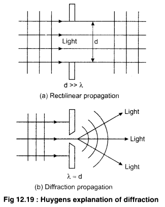
However, if the width of the aperture is comparable to the wavelength of light, most of the incident wavefront will be obstructed and in accordance with Huygens wave theory a cylindrical (a spherical) wavefront depending on the aperture (slit or hole) will originate from it. Now, as the wavefront, after passing through the aperture light will flare out as shown in figure 12.19 (b). This flaring out or spreading of light is the so called diffraction.
Question 5.
Define resolving power of microscope. How does it affect when :
(i) Wavelength of illuminating radiation decreases?
(ii) Diameter of object lens decreases? Give explanation of your answer.
Answer:
The resolving power of a microscope is defined as reciprocal of the smallest distance between two point objects at which they can be just resolved when seen through the microscope.
R.P. of a microscope = \(\frac{1}{d}=\frac{2 n \sin \theta}{\lambda}\)
(i) As R.P. ∝ \(\frac{1}{\lambda}\)
When λ decreases, R.P. increases.
(ii) When the aperture of the objective lens decreases, the semivertical angle θ decreases and hence the resolving power of the microscope increases.
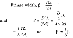
Question 6.
In Young’s double slit experiment if the distance between two slits make four times and distance between slits and screen is halved, then what will be effect on fringe width?
Answer:
Question 7.
Describe structure of Polaroid.
Answer:
Polaroid
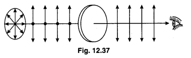
Polarised is a cheap and simple method to obtain plane polarised light. This is a large sized film which is kept between two glass plates. To prepare this film, very small sized crystals of quinine or sulphate or herpethite are set on the sheet of Nitro-cellulose in such a way that their optic axes may remain parallel to each other. These crystals are strong dichroic which absorb one of two refracted rays completely and the second is emerged which is plane polarised. Every Polaroid has its characteristic direction which is known as ‘Polarising Direction’. In figure 12.37 it is shown by parallel lines.
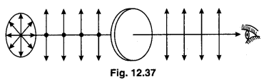
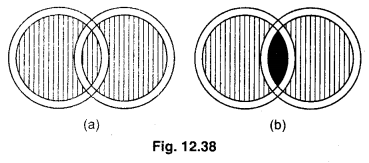
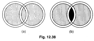
When beam of ordinary light is incident on a Polaroid, the vibrations parallel to its polarising direction, are emerged and those at right angles to above axis are absorbed. Thus the light emerged from the polaroid is plane polarised. To insure the polarisation by polaroid, it is checked by another Polaroid. As shown in figure 12.38, second polaroid is placed on the first one and the intensity of light passing from second polaroid. When second polaroid i. e., the analyser is related about the direction of propagation, the intensity of direction of propagation, the intensity of light is found maximum when the polarising directions of both polaroids are parallel to each other [Figure 12.38 (a)] and intensity is found minimum (about zero) when polarising directions are perpendicular to each other [Figure 12.38]. These observations prove that the light emerged from first polaroid is plane polarised.
Question 8.
What do you understand by double refraction.
Answer:
Nicol Prism
Nicol prism is device, made on the principle of double refraction, which is used to obtain the plane polarised light and it can also be used as analyser. In nicol prism, O-rays of two refracted rays is removed with the help of calcite crystal and only E-ray emerges from it as plane polarised light. Thus the plane polarised light is obtained by nicol prism.
Construction : To form a nicol prism a calcite crystal piece is taken such that its length be three times its width. The faces of width of this crystal are grinded in such a way that the angles of its section become 68° and 112° [Figure 12.36]. This crystal is cut in two pieces such that the cut plane become at right angle to main section. Both cut pieces are polished and then joined with the help of transparent cement of Canada Balsam. Upper and lower faces of obtained crystal are backened.
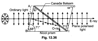
Working : The main section of a nicol prism, shown in figure 12.36, is ABCD. When an unpolarised ray of light PQ is incident on face AB, it breaks up in two refracted rays i, e., in O-ray and E-ray. Both the rays are plane polarised. Refractive index of calcite for O-ray is 1.658 and for E-ray it is 1.468. Refractive index of Canada Balsam is 1.55. Therefore for O-ray, Canada Balsam behaves as rarer medium while for E-ray it behaves as denser medium. When O-ray reaches Canada Balsam layer passing through the crystal, it goes from denser medium to rarer medium. Construction of nicol prism is done in such a way that the angle of incidence for O-ray on Canada Balsam becomes greater than 69°. Therefore, this ray is totally internally reflected and absorbed by the black pointed surface of the nicol prism. For E-ray, Canada balsam behaves as denser medium, therefore it emerges from the crystal which is plane polarised.
Nicol prism is used for obtaining plane polarised light and it can also be used as analyser.
Question 9.
Explain the differences between diffraction and interference.
Answer:
Differences between Interference and Diffraction
- Interference is the result of interaction of light coming from two different wavefronts orginating from two coherent sources, whereas diffraction pattern is the result of interaction of light coming from different parts of the same wavefront.
- In interference, the fringes may or may not be of the same width, while in diffraction, the fringes are always of varying width.
- In interference, the fringes of minimum intensity are perfectly dark (provided light waves are of same amplitude), whereas in diffraction, the fringes of minimum intensity are not perfectly dark.
- In interference, all the bright fringes are of same intensity, while in diffraction, the bright fringes are of varying intensity.
- In the interference pattern, there is a good contrast between bright and dark fringes. On the other hand, in diffraction pattern, the contrast between bright and dark fringes is comparatively poor.
Question 10.
Distinguish between Fresnel and Fraunhoffer diffraction.
Answer:
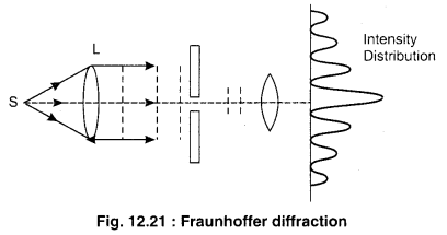
Type of Diffraction : Fresnal and Fraunhoffer Diffraction
The phenomenon of diffraction can be clarified into two categories :
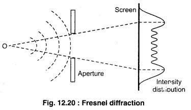
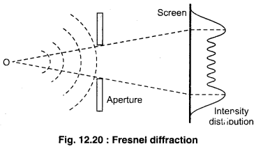
(i) Fresnal diffraction : In this category, the sources and the screen are situated near the obstacle producing diffraction. The beam approaching or going away from the obstacle is not modified by means of a lens or mirror. The wavefronts in this case, are spherical or cylindrical wavefronts.
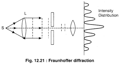
(ii) Fraunhoffer diffraction : In this case, both source and screen are at effective distance from the diffracting device and pattern is the image of source modified by diffraction effects.
RBSE Class 12 Physics Chapter 12 Long Answer Type Questions
Question 1.
Explain the phenomenon of refraction of light on the basis of Huygen’s secondary wavelets theory and verify Snell’s law of refraction.
Answer:
Refraction at Plane Surface
We will now use Huygens principle to derive the laws of refraction. Let PP’ represent the surface separating medium 1 and medium 2 as shown in figure 12.4. Let v1 and v2 represent the speed of light in medium 1 and medium 2, respectively. We assume a plane wavefront AB propagating in the direction A’A incident on the interface at an angle i as shown in the figure. Let t be the time taken by the wavefront to travel the distance BC. Thus,
BC = v1f
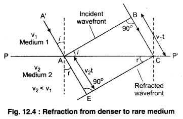
In order to determine the shape of the refracted wavefront, we draw a sphere of radius v2t from the point A in the second medium (the speed of the wave in the second medium is v2). Let CE represent a tangent plane drawn from the point C on the sphere. Then, AE = v2t and CE would represent the refracted wavefront. If we now consider the triangles ABC and AEC, we readily obtain.
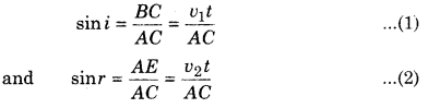
Where i and r are the angles of incidence and refraction, respectively.
From equation (12.1) and (12.2)
\(\frac{\sin i}{\sin r}=\frac{v_{1}}{v_{2}}\) ……………. (3)
From the above equation, we get the important result that if r < i (i.e., if the ray bends toward the normal), the speed of the light wave in the second medium (v2) will be less then the speed of the light wave in the first medium (v1).
This prediction is opposite to the prediction from the corpuscular model of light and as later experiments showed, the prediction of the wave theory is correct. Now, if c represent the speed of light in vacuum, then
n1 = \(\frac{c}{v_{1}}\) …………….. (4)
and n2 = \(\frac{c}{v_{2}}\) …………. (5)
are known as the refractive indices of medium 1 and medium 2 respectively. In term of the refractive indices. Equation (3) can be written as
n1 sini = n2 sinr ……………. (6)
This is the Snell’ law of Refraction. Further if λ1 and λ2 denote the wavelengths of light in medium 1 and medium 2, respectively and if the distance BC is equal to λ1 then the distance AE will be equal to λ2 (because if the crest from B has reached C in time t, then the crest from A should have also reached E in time t), thus
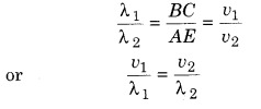
The above equation implies that when a wave gets refracted into a denser medium (v1 > v2) the wavelength and the speed of propagation decrease but the frequency (v = v/λ) remains the same.
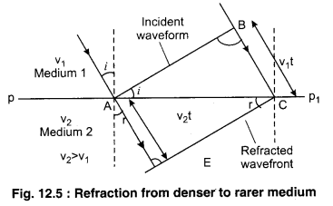
We now consider refraction of a plane wave at a rarer medium, i.e., v1 > v1. Proceeding in an exactly, similar manner we can construct a refracted wavefront as shown in figure 12.5. The angle of refraction will now be greater than angle of incidence; however, we will still have n1 sin i = n2 sinr. We define an angle ic by the following equation
sin ic = \(\frac{n_{2}}{n_{1}}\)
Thus, if i = ic, then sinr = 1 and r = 90°.
Obviously, for i > ic, there can not be any refracted wave. The angle ic is known as the critical angle and for all angles of incidence greater than the critical angle, we will not have any refracted wave and the wave will undergo what is known as total internal reflection.
Question 2.
Describe the reflection of light on the basis of Huygens’ wave theory.
Answer:
Reflection at Plane Surface
As shown in figure, consider a plane wavefront AB incident on the plane reflecting surface AY, both the wavefront and the reflecting surface being perpendicular to the plane of paper.
First the wavefront touches the reflecting surface at B and then at the successive points towards C. In accordance with Huygens principle, from each point on BC, secondary wavelets start growing with the speed c. During the time the disturbance from A reaches the point C, the secondary wavelets from B must have spread over a hemisphere of radius BD = AC = vt, where t is the time taken by the disturbance to travel from A to C. The tangent plane CD drawn from the point C over this hemisphere of radius vt will be the new reflected wavefront.
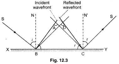
Let angles of incidence and reflection be i and r respectively. In ∆ABC and ∆DCB, we have
∠BAC = ∠CDB (each is 90°)
BC = BC (common)
AC = BD (each is equal to ct)
∆ABC ≅ ∆DCB
Hence, ∠ABC = ∠DCB
∴ i = r
i.e., the angle of incidence is equal to the angle of reflection. This proves the first law of reflection.
Further, since the incident ray SB, the normal BN and the reflected ray BD are respectively perpendicular to the incident wavefront AB the reflecting surface XY and the reflected wavefront CD (all of which are perpendicular to the plane of the paper), therefore, they all lie in the plane of the paper, i.e., in the same phase. This proves the second law of reflection.
Question 3.
Describe analytically phenomenon of interference of light and explain constructive and destructive interference.
Answer:
Interference of Two Waves
“When the two waves of same frequency coming from coherent sources and travelling in same direction, superimpose each other, the resultant intensity, in general, is different from the sum of individual intensities of the waves. At some places, the resultant intensity is greater then the sum of individual intensities and at some other places, resultant intensity is less than the sum of individual intensities. The event of this rise and fall in resultant intensity, in the region of superimposition, is known as ‘Interference’.
Where the resultant intensity is greater than the sum of individual intensities, the interference taking place there is called “Constructive interference’. On the other hand, where the resultant intensity is less than the sum of individual intensities, the interference taking place there is called “Destructive interference”.
Mathematical Analysis : Suppose the equations of two waves of same frequency (ω = 2πn) are as under :
y1 = a sinωt ………… (1)
and y2 = b sin(ωt + ϕ) ……………. (2)
Where a and b are the amplitudes of the waves and (ϕ) is the phase difference between them. If these waves superimpose each other,then from the principle of superimposition,
y = y1 + y1
or y = a sin ωt + b sin(ωt + ϕ)
= a sinωt + b sinωt cosϕ + bcosωt sinϕ
= (a + b cosϕ) sin ωt + b sin ϕ. cos ωt
or y = A cosθ.sinωt + A sinθ.cosωt
Where A cosθ = a + b cosϕ ……….. (3)
and A sinθ = b sin ϕ) ……….. (4)
∴ y = A [sinωt cosθ + cosωt sinθ]
or y = A sin [ωt + θ] ……….. (5)
This is the equation of resultant wave where A is its amplitude.
Resultant Amplitude : To get the resultant amplitude, on adding the squares of equation (3) and (4),
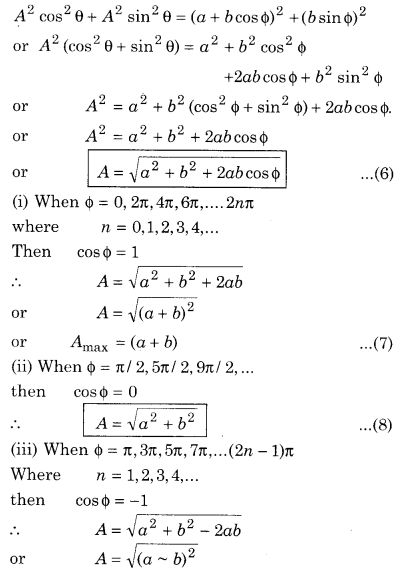
or, A = (a ~ b) ………….. (9)
or, Amin = (a ~ b)
Similarly other values of A can be calculated.
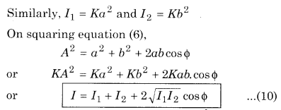
Resultant Intensity :
∵ Intensity ∝ (Amplitude)2
∴ I ∝ A2 or I = KA2
Question 4.
What do you understand by diffraction of light? Why is it easy to see diffraction of sound waves compare to light waves? Differentiate between Fresnel and Fraunhoffer diffraction.
Answer:
Diffraction
Consider a source of light S emitting in all directions. Let a screen be placed at some distance from it. Place an opaque obstacle in between S and screen. According to geometrical considerations, light should be there on the screen above A’ and below B. There is supposed to be complete darkness in between A’ and B. Experimental observations, however, indicate that some light is present immediately below A’ and above B. Newton’s Corpuscular Theory, according to which light travels in a straight line, could not afford an explanation to this experimental observation.
The phenomenon of bending of light wave around corners and the spreading of light waves into the geometrical shadow of object is called diffraction.
Grinaldi of Italy in the 17th century discovered that if the size of an obstacle or operature is comparable with the wavelength of light, light deviates from rectilinear propagation near the edges of the obstacle (or aperture) and enters the geometrical shadow. This flaring out or encronchment of light in the shadow zone as it passes around obstacles or through small aperatures is called diffraction.
As a result of diffraction, the edges of the shadow (or illuminated region) do not remain well defined and sharp but become blurred and fringed.
Fresnel was able to explain the phenomenon of diffraction by making a blend of Huygens principle and phenomenon of interference.
Comparison of Diffraction of Sound and Light
The wavelength of light rays is of the order of 10-7 m. It is very small comparatively to dimensions of general obstacles, so that it is impossible to diffraction phenomenon taking place. This is due to the cause that we hear the sound coming from television set placed in nearly room but we cannot see images of television. Diffraction is characteristic phenomenon of wave. In higher classes you will read about diffraction of X-rays.
Diffraction is explained on the basis of Huygens wave theory of light. If the size of the aperture (or diffracting obstacle) is much larger than the wavelength of light the incident plane wavefront will pass through the slit without change in its shape and direction of motion as shown in figure 12.19 (a) resulting in rectilinear propagation of light.
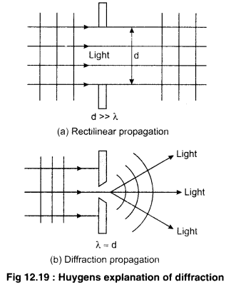
However, if the width of the aperture is comparable to the wavelength of light, most of the incident wavefront will be obstructed and in accordance with Huygens wave theory a cylindrical (a spherical) wavefront depending on the aperture (slit or hole) will originate from it. Now, as the wavefront, after passing through the aperture light will flare out as shown in figure 12.19 (b). This flaring out or spreading of light is the so called diffraction.
Type of Diffraction : Fresnal and Fraunhoffer Diffraction
The phenomenon of diffraction can be clarified into two categories :
(i) Fresnal diffraction : In this category, the sources and the screen are situated near the obstacle producing diffraction. The beam approaching or going away from the obstacle is not modified by means of a lens or mirror. The wavefronts in this case, are spherical or cylindrical wavefronts.
(ii) Fraunhoffer diffraction : In this case, both source and screen are at effective distance from the diffracting device and pattern is the image of source modified by diffraction effects.
Question 5.
Explain the phenomenon of diffraction of light at a single slit.
Answer:
Fraunhoffer Diffraction due to a Single Slit
As shown in figure 12.22 a source S of monochromatic light is placed at the focus of a convex lens Li. A parallel beam of light and hence a plane wavefront WW’ gets incident on a narrow rectangular slit AB of width a.
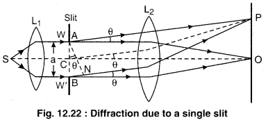
The incident wavefront disturbs all parts of the slit AB simultaneously. According to Huygens, the all parts of the slit AB will become source of secondary wavelets, which all start in the same phase. These wavelets spread out in all directions, thus causing diffraction of light after it emerges through slit AB. Suppose the diffraction pattern is focussed by a convex lens L2 on a screen placed in its focal plane.
All the secondary wavelets going straight across the slit AB are focussed at the central point O of the screen. The wavelets from any two corresponding points of the two halves of the slit reach the point O in the same phase, they add constructively to produce a central bright fringe.
Suppose, the secondary wavelets diffracted at an angle are focused at point P. The secondary wavelets start from different parts of the slit in same phase but they reach the point P in different phases. Draw perpendicular AN from A on to the ray from B. Then the path difference between the wavelets from A and B will be
BN = p = BP – AP = BM = ABsinθ = a sinθ
Let the point P be so located on the screen that the path difference p = λ and angle θ = θ1, then from the above equation, we get
a sin θ1 = λ
We can divide the slit ABinto two halves AC and CB. The path difference between the wavelets from A and C will be \(\frac{\lambda}{2}\). Similarly, corresponding to every point in the upper half AC , there is a point in the lower half CB for which the path difference is \(\frac{\lambda}{2}\). Hence the wavelets from the two halves reach the point P always in opposite phases. They interfere distructively so as to produce a minimum.
Thus the condition for first dark fringe is
a sin θ1 = λ
Similarly, the condition for second dark fringe will be
a sin θ2 = 2λ
Hence the condition for nth dark fringe can be written as
a sin θn = nλ, n = 1,2,3,………….. (1)
The directions of various minima are given by
θn ≈ sinθn = \(m \frac{\lambda}{a}\)
[As λ < < d, so sinθn = θn]
Now for the positions of secondary maxima suppose the point P is so located that
p = \(\frac{3 \lambda}{2}\)
When θ = θ’1
then a sin θ’1= \(\frac{3}{2} l\)
We can divide the slit into three equal parts. The path difference between two corresponding points of the first two parts will be \(\frac{\lambda}{2}\). The wavelets from these points will interfere destructively. However, the wavelets from the third part of the slit will contribute to some intensity forming a secondary maximum. The intensity of this maximum is much less than that of the central maximum.
Thus the condition for the first secondary maximum is
a sin θ’1 = \(\frac{3}{2} \lambda\)
Similarly, the condition for the second secondary maximum is
a sin θ’2 = \(\frac{5}{2} \lambda\)
Hence the condition for nthsecondary maximum can be written as
d sin θ’n = (2n + 1)\(\frac{\lambda}{2}\) , n = 1, 2, 3,…………. (2)
The directions of secondary maxima are given by
θ’n = sin θ’n = (2n + 1)\(\frac{\lambda}{2d}\), n = 1, 2, 3, ………….. (3)
The intensity of secondary maxima decreases as n increases.
Question 6.
What is polarisation? Explain polarisation with the help of electric vector. Clarify why is it a characteristic of transverse waves.
Answer:
Polarisation of Light
Exhibition of interference and diffraction by light process that the nature of light is wave nature but which type of waves, whether longitudinal or transverse, are the light waves, this information is given by polarisation only. Phenomenon of polarisation proves the transverse nature of light waves because polarisation is possible only in transverse waves and light waves show the phenomenon of polarisation. Scientist Huygens invented the phenomenon of polarisation in 1690 and he had to give up his primary idea of light waves to be longitudinal because polarisation can not be explained on the basis of longitudinal wave theory of light. In 1830, Fresnel justified the transverse nature of light waves.
Experimental proof of transverse nature of light waves : To prove the transverse nature of light waves we take two tourmaline crystale N1 and N2. The chemical name of tourmaline is aluminium boron silicate and is transparent for light. These crystals are cut in such a way that their axes be in their plane.
When ordinary light is incident on crystal N1, the emergent light appears somewhat greenish. Now, if N1 is rotated about the direction of propagation of light, there is no change in the intensity of emergent light. This event proves that the vibrations of light wave are symmetrical in all directions at right angles to the direction of propagation.
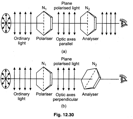
Now crystals N1 and N2 are placed in such a way that the optic axes of both the crystals be parallel to each other [Figure 12.30 (a)]. When the light is incident normally on N1 the intensity of light emerging from N2 is maximum. Now if crystal N2 is rotated in its own plane about the direction of propagation of light, the intensity of light emerging from N2 goes on decreasing and becomes zero when the axes of both the crystals become perpendicular to each other and darkness is observed in area of vision [Figure 12.30 (b)]. Again if crystal N2 is rotated in the same direction, the emergent intensity from N2 goes on increasing and again it becomes maximum when the axes of both the crystals again become parallel to each o.ther. Similar observations are obtained when N1 is rotated and N2 kept stationary.
Thus, it is clear from this experiment that propagation of light is in the form of transverse waves. If the light waves were longitudinal, the intensity of light emerging from N2 would have been uneffected with its all positions.
First crystal N1 is known as ‘Polariser’ and N2 is called ‘Analyser’ because this cyrstal examine the light emerging from N1 whether it is polarised or not?
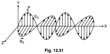
Explanation of Tourmaline-Experiment : According to Maxwell’s electromagnetic wave theory the light waves are electromagnetic waves not the mechanical waves. A hypothetical medium ether is needed for propagation of these waves. In these waves, two field vectors, electric field vector (\(\vec{E}\)) and magnetic field vector (\(\vec{B}\)), vibrate at right angles to each other remaining perpendicular to direction of propagation of electromagnetic wave [Figure 12.31]. Electric field vector (\(\vec{E}\)) is responsible to all light effects, hence it is also known as Tight vector’. Since both the field vectors are perpendicular to direction of propagation, the light waves are transverse in nature.
Now we shall explain the experiment performed with tourmaline crystals on the basis of Electromagnetic Wave Theory. Since the light waves are transverse in nature, therefore the vibrations of light vector are found symmetrical around the direction of propagation. This is why when ordinary light is passed through a tourmaline crystal, there is no change in intensity of emergent light on rotating the crystal because in all situations of the crystal the light vector remains available parallel to its optic axis. Here one fact is rememberable that only the vibrations along the optic axis are emerged from the crystal. Thus the vibrations in emerged light are only in one plane, therefore it is known as ‘plane plarised light’. Clearly, the lack of symmetry in the vibrations of emerged light is produced by the crystal. This phenomenon is called the polarisation of light.
When the light emerged from N1 is allowed to incident on N2 and the optic axes of both the crystals are parallel, then all the vibrations coming from N1 are emerged by N2 and the intensity is maximum. When N2 is rotated, then only the component of vibrations along the optic axis of N2 is emerged and thus the intensity varies. Ultimately the emergent intensity by N2 becomes minimum (t.e., approximately zero) as the axes of N1 and N2 because perpendicular to each other. In this position both the crystals are said to be crossed. Thus the intensity of emergent light depends on the inclination of both axes.
Question 7.
Write four methods to produce polarised light. Define double refraction and explain it.
Answer:
Methods to produce polarised light.
(1) Polarisation by Reflection
(2) Polarisation by Scattering
(3) Polarisation by Double Refraction
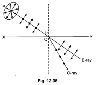
Polarisation by Double Refraction :
There are some crystals like calcite and quartz of such type, when a ray of ordinary light is incident upon them, it breaks up into parts inside the cyrstal [figure 12.35], This phenomenon is known as double refraction. One of these two refracted rays, obeys the general laws of refraction and is called, ‘Ordinary-ray’ or ‘O-ray’ and the other do not obey the laws of refraction, is called ‘extra ordinary ray’ or ‘E-ray’. Both the rays are plane polarised in planes perpendicular to each other. In O-ray, the vibrations are in plane perpendicular to plane of incidence and in E-ray the vibrations are in plane of incidence. By any means, one of these two rays is removed so that plane polarised light may be obtained from the crystal.
Question 8.
How can you obtain plane polarised light using reflection? What is Brewster’s law? Prove that when an unpolarised light is incident on a plane glass surface, then reflected and refracted rays are 90° to each other.
Answer:
Production of Plane Polarised Light
(1) Polarisation by Reflection : French engineer Malus invented in 1808, when ordinary light is reflected by surface of transparent medium (e.g., glass), it becomes partly plane polarised. In 1811, scientist ‘Brewster’ studied this event in detail and concluded and told that the quantity of polarised light in reflected light depends on the angle of incidence. On changing the angle of incidence, a certain angle of incidence is obtained for which the reflected light is completely plane polarised. This particular angle is known as the ‘angle of polarisation’ or ‘Brewster’s angle’ and it is denoted by ip. This angle is certain for a particular medium and different for different media. For water its value is about 53°and for glass it is 57°. If the refractive index of transparent medium be n, then according to brewster n and ip will be related as
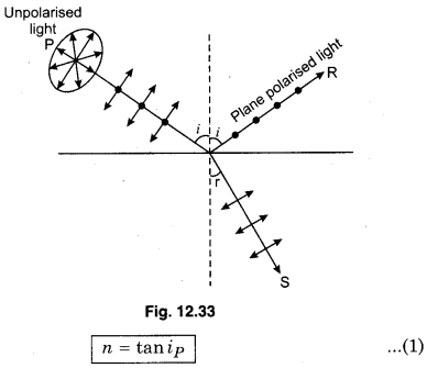
This formula is known as ‘Brewster’s law’.
When the light is incident at this angle, the reflected and refracted rays are at right angles to each other.
This fact can be proved as under :
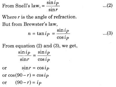
or ip + r = 90° …………. (4)
From figure 12.33, ip + θ + r = 180°
or θ + 90° = 180°
or θ = 180° – 90° = 90°
or θ=90° ………… (5)
Clearly, reflected and refracted rays are at right angles to each other.
If it is given that ip + r = 90°
Then relation between ip and n will be established as under :
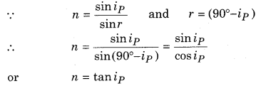
This very relation is Brewster’s law.
Question 9.
Give definition of ‘plane of vibration’ and ‘plane of polarisation’. Define Malus law and explain the parallel and cross condition of Polaroid.
Answer:
The plane containing the direction of vibration and the direction of wave propagation is called the plane of vibration.
As shown in figure, if light wave is propagating along X-axis and the electric field vector vibrates parallel to Y-axis then ABCD or XY-plane is the plane of vibration.
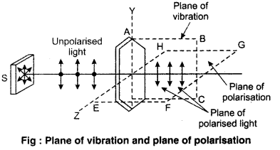
In figure, EFGH or XZ-plane is the plane of polarisation
Polaroid
Polarised is a cheap and simple method to obtain plane polarised light. This is a large sized film which is kept between two glass plates. To prepare this film, very small sized crystals of quinine or sulphate or herpethite are set on the sheet of Nitro-cellulose in such a way that their optic axes may remain parallel to each other. These crystals are strong dichroic which absorb one of two refracted rays completely and the second is emerged which is plane polarised. Every Polaroid has its characteristic direction which is known as ‘Polarising Direction’. In figure 12.37 it is shown by parallel lines.
When beam of ordinary light is incident on a Polaroid, the vibrations parallel to its polarising direction, are emerged and those at right angles to above axis are absorbed. Thus the light emerged from the polaroid is plane polarised. To insure the polarisation by polaroid, it is checked by another Polaroid. As shown in fig-ure 12.38, second polaroid is placed on the first one and the intensity of light passing from second polaroid. When second polaroid i. e., the analyser is related about the direction of propagation, the intensity of direction of propagation, the intensity of light is found maximum when the polarising directions of both polaroids are parallel to each other [Figure 12.38 (a)] and intensity is found minimum (about zero) when polarising directions are perpendicular to each other [Figure 12.38]. These observations prove that the light emerged from first polaroid is plane polarised.
Intensity of Light Emerged from the Polaroid : If I0 be the intensity of incident light on the polaroid. the intensity of emerged light is,
I = I0 cos2 θ …………. (1)
Where θ is the angle between the polarising direction of the polaroid and light vector. This is also known as ‘Malus’s law’.
If the light incident on the polaroid is unpolarised, the vibrations of light vector will be similar in all directions in the plane perpendicular to direction of propagation. Therefore, average value of cos2(i.e.\(\frac{1}{2}\)) will be substituted in equation (1)
∴ I = \(\frac{1}{2}\) I0 ………… (2)
Clearly, in this position, the intensity of emergent light becomes half of incident intensity.
If the light emerging from one polaroid (intensity I1) is incident on second polaroid,the intensity of light emerging from second polaroid will be :
I2 = I1 cos2 θ ………….. (3)
Where θ is the angle between the polarising directions of.both the polaroids.
If both polaroids are in parallel position, then θ = 0 and cos2 θ = 1
∴ I2 = I1 = \(\frac{1}{2}\) I0 (maximum, intensity)
In crossed position, θ = 90°, ∴ cos2 θ = 0
∴ I2 = 0 (minimum intensity)
RBSE Class 12 Physics Chapter 12 Numerical Questions
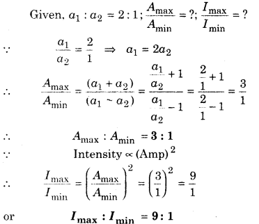
Question 1.
Two waves of same shape have amplitude ratio 2 : 1. In interference region find out the ratio of maximum and minimum amplitude of vibrations and ratio of intensities.
Solution:
Question 2.
In an interference experiment, two sources of light are used of intensities 7 and 47. Find out the intensities at those points where the phase difference of two waves superimposing are
(a) zero
(b) \(\frac{\pi}{2}\)
(c) π .
Solution:
Given, I1 = I1I2 = 4I; IR = ?
(a) When ϕ = 0, then IR = 0
∵ Resultant intensity
IR = I1 + I2 + \(2 \sqrt{I_{1} I_{2}}\) cos ϕ
∴ IR = I + 4I + \(2 \sqrt{1 \times 4 I}\) × cos 0
= I + 4I + 4I
or IR = 9I
(b) When ϕ = \(\frac{\pi}{2}\) then cos ϕ = 0
∴ IR = I + 4I + 0 = 5I
or IR = 5I
(c) when ϕ = π, then cos ϕ = -1
∴ IR = I + 4I + \(2 \sqrt{I \times 4 I}\) × (-1)
= I + 4I – 4I
or IR = I
Question 3.
Find out the distance between two aperture, which are placed at 1 m distance from screen and from fringes of width 1 mm, while wavelength of light is 5000 A.
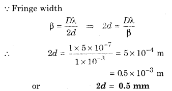
Solution:
Given, d = ?; D = 1 m; β = 1 mm = 1 × 10⁻³ m;
λ = 5000 Å = 5 × 10⁻⁷ m
Question 4.
The light of wavelength 5500 Å is falling normally on an aperture of width 22 × 105cm. Find the angular positions between two minima on both side of central maxima.
Solution:
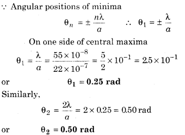
Given, λ = 5500 Å = 5500 × 10-10
m = 55 × 10-8 m; α = 22 × 10-5 cm = 22 × 10-7 m;
θ1 =?; θ2 =?
Question 5.
Two polaroids are so placed, such that the emerging light from them has maximum intensity. If one polaroid is rotated through 30°, from 90° with respect to other, then find out the ratio of part of the emerging light compared with light of maximum intensity.
Solution:
First two polaroids are in parallel oriented so maximum intensity emergent from second will same as first. When θ = 30°, then
Emergent intensity
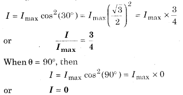
Question 6.
When Sun is at 37° angle from horizon, then reflected light from water surface is totally polarised. Find refractive index of water.
Solution:
Light reflected from water is polarised. Therefore incident angle will be polarising angle.
∴ ip = 90 – 37° = 53°
From Brewster’s law,
Refractive index of water . 4
μ = tan ip = tan 53°= \(\frac{4}{3}\) or μ = 1.33
Question 7.
Polarising directions of two polarising plates are parallel and intensity of light is maximum. How much one plate be rotated that intensity of emerging out light becomes one fourth?
Solution: