Rajasthan Board RBSE Class 12 Physics Chapter 6 Electric Circuit
RBSE Class 12 Physics Chapter 6 Text Book Exercise with Answers
RBSE Class 12 Physics Chapter 6 Multiple Choice Type Questions
RBSE Solutions For Class 12 Physics Chapter 6 Question 1.
Kirchhoffs first and second laws are based on :
(a) Charge and Energy Conservation Laws
(b) Current and Energy Conservation Laws
(c) Mass and Charge Conservation Laws
(d) None of these
Answer:
(a) Charge and Energy Conservation Laws
Kirchhoffs first law is based on law of conservation of charge and second law is based on law of conservation of energy.
RBSE Class 12 Physics Chapter 6 Question 2.
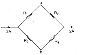
The potential difference between the points a and b in given figure will be :
(a) R1 – R2
(b) R2 – R1
(c) \(\frac{R_{1} R_{2}}{R_{1}+R_{2}}\)
(d) Zero
Answer:
(a) R1 – R2
I1 = I 2 = 1 amp
∴ Potential at a, Va = I1 × R1
= 1 × R1 = R1
Potential at b, Vb = I2R2 = 1 × R2 = R2
Va – Vb = R1 – R2
RBSE Solutions For Class 12 Physics Question 3.
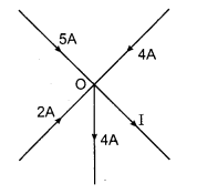
The value of I in a given figure will be :
(a) 6 A
(b) 11 A
(c) 7 A
(d) 5 A
Answer:
(c) 7 A
From first law of Kirchhoff,
ΣI = 0
5 + 2 + 4 – 4 – I = 0
I = 7 A
RBSE Solutions Physics Class 12 Question 4.
In a Wheatstone bridge, the position of battery and galvanometer is interchanged, then the new balanced position will be :
(a) Unchanged
(b) Will changed
(c) Can’t say anything
(d) May change or may not be, it depends upon the resistance of galvanometer and battery
Answer:
(a) Unchanged
There will be no effect
RBSE Solution Class 12 Physics Question 5.
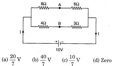
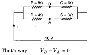
The potential difference between the points a and b in a given figure is :
Answer:
(d)
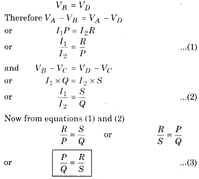
In the circuit \(\frac{P}{Q}=\frac{R}{S}\)
∴ \(\frac{8}{4}=\frac{6}{3}\) = true
So the circuit work as Wheatstone Bridge
RBSE Solution Class 12th Physics Question 6.
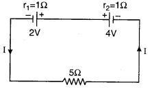
The current flow in a given circuit will be :
(a) 2.5 A
(b) 0.75 A
(c) 0.5 A
(d) 0.25 A
Answer:
(d) 0.25 A
From Kirchhoff’s second law
ΣE = IR
2 – 4 = -2I – 5I – I
-2 = -8I
I = \(\frac{2}{8}\frac{1}{4}=\) = 0.25 A
Physics Class 12 RBSE Solutions Question 7.
Potentiometer is a type of instrument by which potential difference can be measured; then its resistance will be ;
(a) Zero
(b) Infinite
(c) Uncertain
(d) Depends on external resistance
Answer:
(b) Infinite
Effective resistance of potentiometer is infinite.
RBSE Solutions Class 12 Physics Question 8.
The physical quantity which can not be measured with the help of potentiometer is :
(a) EMF of cell.
(b) Inductance and capacitance
(c) Resistance
(d) Electric current
Answer:
(b) Inductance and capacitance
Capacitance and self inductance are not measured with the help of potentiometer.
Class 12 Physics RBSE Solutions Question 9.
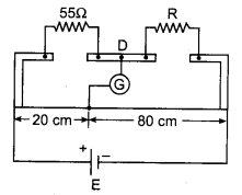
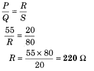
In the circuit zero deflection is shown in figure in meter bridge experiment. Find out the resistance R:
(a) 220 Ω
(b) 110 Ω
(c) 55 Ω
(d) 13.75 Ω
Answer:
(a) 220 Ω
RBSE Solutions For Class 12th Physics Question 10.
Temperature coefficient of resistance of potentiometer wire should be :
(a) High
(b) Low
(c) Negligible
(d) Infinite
Answer:
(c) Negligible
The specific resistance and the coefficient of linear expansion of potentiometer wire must be negligible.
RBSE Solution Physics Class 12 Question 11.
Formula of internal resistance of primary cell in the form of balancing length is {l1and l2 are the balancing lengths in open and closed circuit respectively} :
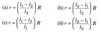
Answer:
(a)
r = \(\left(\frac{l_{1}-l_{2}}{l_{2}}\right)\)R
12 Physics RBSE Solutions Question 12.
Cell of emf e is balanced at length L in potentiometer experiment. Now other cell having emf e connects parallel to the first cell. Now the new balancing length will be :
(a) 2L
(b) L
(c) \(\frac{L}{2}\)
(d) \(\frac{L}{4}\)
Answer:
(b) L
In parallel combination there will be no effect on potential difference. So there will be no effect on balance length.
12th Physics RBSE Solutions Question 13.
The standard cell of 1.1 V is balanced on 2.20 m length in potentiometer. Potential difference across any resistance is balanced at 95 cm and voltmeter shows 0.5 V reading then error in the reading of voltmeter will be :
(a) +0.025 V
(b) +0.525 V
(c) -0.025 V
(d) -0.525 V
Answer:
(a) +0.025 V
Potential drop measured by potentiometer
V2 = \(\frac{E}{L}\) × R2
= \(\frac{1.1}{2.20} \times \frac{95}{100}\) = 0.475V
Potential difference measured by voltmeter = 0.5 volt
Error in the reading of voltmeter
ΔV = V – V’
ΔV = 0.500 – 0.475
= + 0.025 volt
RBSE Class 12 Physics Chapter 6 Very Short Answer Type Questions
RBSE Solutions Class 12th Physics Question 1.
Write the mathematical form of Kirchhoff’s junction law.
Answer:
The mathematical form of Kirchhoff’s junction law, ΣI = 0
RBSE Solutions 12 Physics Question 2.
Kirchhoff’s voltage law is based on which conservation law?
Answer:
Law of conservation of energy.
Class 12th Physics RBSE Solutions Question 3.
Write the condition of the balanced state of the Wheatstone bridge.
Answer:
When the Wheatstone bridge is balanced, then the ratio of the resistances of ratio arms are equal.
\(\frac{P}{Q}=\frac{R}{S}\)
RBSE Solutions For Class 12 Maths Chapter 6 Question 4.
What is the principle of meter bridge?
Answer:
Meter bridge is based on the principle of Wheatstone bridge.
RBSE Solutions 12th Physics Question 5.
Why the potential gradient of the wire of potentiometer is based on the temperature?
Answer:
When the temperature of the potentiometer wire increases its resistance also increases so that its potential gradient affected.
12th Physics RBSE Solution Question 6.
If the emf of unknown cell in secondary circuit is greater than the emf of primary circuit of potentiometer then what will happen?
Answer:
Null point will not be found on potentiometer wire.
RBSE Solution Of Class 12th Physics Question 7.
Write down the definition of the potential gradient.
Answer:
Potential drop per unit length of the wire of potentiometer is known as potential gradient of potentiometer.
Potentiometer Formula Class 12 Question 8.
Why the cross-sectional area of the wire should be uniform in a potentiometer?
Answer:
So that the potential gradient remains constant at all positions.
Question 9.
Which cell can be used for standardization of the potentiometer other than Daniel cell?
Answer:
Cadmium cell or Leclanche cell. ’
Question 10.
How can the sensitivity of the potentiometer be increased?
Answer.
Potential gradient k = \(\frac{V_{A B}}{l_{A B}}\)
So, the sensitivity of potentiometer can be increased by increasing the length of the wire of potentiometer.
Question 11.
Length of the potentiometer wire is 10 m. A standard cell of 1.1 V is balanced at 8.8 m length. How much maximum potential difference can be measured with the help of this potentiometer?
Answer:
Potential gradient (k) = \(\frac{V}{l}=\frac{1.1 V}{8.8}\)
= 0.125 V/ m
Maximum potential difference
V = kl = 0.125 × 10 = 12.5 volt
Question 12.
Why copper wire can not be used in potentiometer?
Answer:
Temperature coefficient of resistance is large and specific resistance is less for the copper wire.
Question 13.
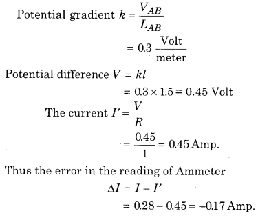
The potential gradient of the wire of potentiometer is 0.3 V/m. In the calibration of ammeter, potential difference across 1 Ω coil is balanced at 1.5 m length. If the reading of ammeter is 0.28A then find out the error in the reading of ammeter.
Answer:
Virtual current is measured by Ammeter I = 0.28 A
RBSE Class 12 Physics Chapter 6 Short Answer Type Questions
Question 1.
Write the statement of Junction and Loop Law of Kirchhoff s.
Answer:
“In an electric circuit, the algebraic sum of current at any junction point must be zero.”
i. e., ΣI = 0
The sum of currents entering a junction is equal to the sum of currents leaving out at the junction. This law is called Kirchhoff s First Law or Junction Law.
It is based on the law of Conservation of Charge. When currents in a circuit are steady, charges can not accumulate at any junction. So whatever charge flows towards the junction in any time interval, an equal charge must flow away from that junction in the same time interval.
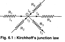
In figure (6.1) at junction O,
I1 + I2 – I3 – I4 + I5 = 0
or I1 + I2 + I5 = I3 + I4 ………………. (1)
In figure (6.1) the currents flowing towards the junction are taken as positive and current flowing away from the junction are taken as negative.
Kirchhoff’s Second Law or Loop Law
This law is applicable for closed electrical circuit. The algebraic sum of the potential in a closed loop must be zero.
i.e., ΣV = 0 …………… (1)
The algebraic sum of the emf’s in any loop of a circuit is equal to the sum of the voltages across the resistance.
ΣE = ΣIR ………….. (2)
Sign convention for applying Loop Rule
1. The product of current and resistance (IR) is taken as positive if the resistor is traversed in the same direction of assumed current. The product of current and resistance (IR) is taken as negative if the resistor is traversed in the opposite direction of assumed current.
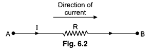
In loop we can move from A to B then the product of IR take as positive VAB = +IR. [In the direction of current]
In a loop we can move from B to A then the product of IR take as negative.
∴ VBA = -IR [Opposite direction of current]
2. When we move from B to A then E is taken positive (+). When we move from AtoB, then E is taken negative (-).

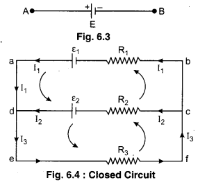
Loop law can be understood by the figure 6.4.
In the given figure for point d by the Junction Law, current flowing through the resistance R% will be
I3 = I1 + I2 …………… (3)
In the loop adcba by the Kirchhoff s Loop Law.
I1R1 – I2R2 = ε1 – ε2
or I2R2 = I2R2 = ε2 – ε1 ………… (4)
In the loop defcd by the Loop Law
I3R3 + I2R2 = ε2 …………….. (5)
By solving equations (3), (4) and (5) we can find out electric currents in different branches as well as we can find potential differences across the resistance.
Question 2.
Write the process of finding unknown resistance by meter bridge and deduce the necessary mathematical formula.
Answer:
Meter Bridge
It is the simplest practical application of the Wheatstone bridge that is used to measure an unknown resistance.
Construction : It consists of usually one meter long Manganin or constant on wire of uniform cross-sectional area, stretched along a meter scale fixed over a wooden board and with its two ends soldered to two L- shaped thick copper strips M and N. Between these two copper strips, another copper strip I is fixed so as to provide two gaps ab and a1b1. A resistance box R.B. is connected in the gap ab and the R.B. G unknown resistance S is connected to the gap ab. and the unknown resistance S is connected to the gap a1b1. A source of emf e is connected across AC. A movable jockey and a galvanometer are connected at BD as shown in the figure.
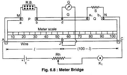
Working : After taking out a suitable resistance R from the resistance box, we touch the jockey at point A and C and observe opposite deflection in galvanometer. If galvanometer shows deflection in one direction then we change the value of known resistance until galvanometer shows opposite deflection.
Now the jockey is moved along the wire AC till there is no deflection in the galvanometer. This is the balanced condition of the Wheatstone bridge. If P and Q are the resistances of the parts AB and BC of the wire, then for the balanced condition of the bridge we have
\(\frac{P}{Q}=\frac{R}{S}\) ……………….. (1)
If resistance of unit length of the wire is \(\sigma \frac{\mathrm{ohm}}{\mathrm{cm}}\) and the balance point occurs at l cm from A then the length of part BC will be (100 – l) cm.
P = Resistance of wire of AB part = σl …………. (2)
Q = Resistance of wire of BC part = σ (100 – l) ……………… (3)
In equation (1) putting the value P and Q
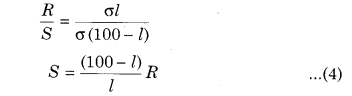
Knowing l and R, unknown resistance can be determined.
The formula of determination of specific resistance of unknown resistannce (S)
We know that
Unknown resistance (S) = \(\rho \frac{l^{\prime}}{A}\)
Where l’ = Length of unknown resistance
A = Area of cross section = πr2
From equation (4)
Limitations of Meter Bridge :
- Copper strips have their own resistances but in the calculation of meter bridge formula we neglect this resistance so that our results are errorful. For minimising this error, at time of performing experiment we should calculate unknown resistance by interchanging the position of unknown resistance and known resistance. In this process we take average value of obesrvations by which error can be minimised.
- The resistances of end points affect the sensitivity of meter bridge. To nulify this effect Carey-Foster s bridge is used.
- Current should not flow for long time through the wire otherwise wire will heat up and the resistance of wire will be changed.
- Jockey should not slide tightly on resistance wire otherwise it’s cross-section area will change. That is why the resistance of the wire will be changed.
Question 3.
What is Wheatstone bridge? Deduce the balanced condition of it with the help of Kirchhoff’s law.
Answer:
Construction : The construction of Wheatstone’s bridge is shown in following diagram (figure 6.5) in which a quadrilateral ABCD is prepared by
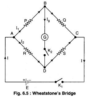
connecting four resistances P, Q, R and S. A cell is connected between the points A and C through key K1 which is known as battery key and a galvanometer between the point B and D through another key K2 which is known as galvanometer key. If on pressing the key K1 and K2, there is no deflection in galvanometer, then the bridge is said to be balanced condition. In this situation the relation between all the resistances is given by :
\(\frac{P}{Q}=\frac{R}{S}\)
Principle of Wheatstone Bridge and Condition of Balance
When battery key K1 is pressed, then main current I starts flowing in the circuit. At junction A this current splits in two parts I1 and I2 as shown in figure 6.6. These currents I2 and I2 again obtain two paths at junctions B and D respectively. Now following three situations are possible :
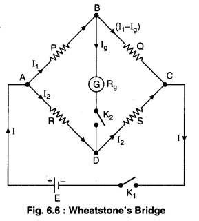
(i) When VB > VD. then current I2 passes as such through resistance S but current I1 splits in two parts at junction B, one part Ig passes through galvanometer showing deflection in one direction while rest current (I1 – Ig) passes through Q.
(ii) When VB < VD. then opposite situation to previous situation (i) is observed i.e. .current I2 splits in two parts at D. Now the current Ig produces deflection in galvanometer in opposite direction to previous deflection.
(iii) When VB = VD, then no current passes through galvanometer i.e. galvanometer shows no deflection because now I g = 0. This situation is said to be balance condition of Wheatstone bridge. It is clear that current is flowing in the circuit but there is no effect of current on galvanometer arm which resembles with the bridge on a river. This is why this circuit is called ‘Bridge circuit’ Thus in balanced condition.
Therefore, “it is clear that in balanced situation of the bridge, the ratio of resistances of any two corresponding arms of quadrilateral ABCD is equal to ratio of two remaining corresponding arms”.
From equation (3).
S = \(\frac{Q}{P} \times R\)
Thus, by determining the balanced situation, unknown resistance can be determined.
The arms of Wheatstone bridge are known as particulars names given below :
(i) P and Q are called ratio arms.
(ii) R is called variable resistance arm.
(iii) S is called unknown resistance arm.
Question 4.
What is potential gradient? On which factors potential gradient depends?
Answer:
Principle of Potentiometer
Potentiometer : Potentiometer is a apparatus with help of which the e.m.f. of a cell and potential difference can be measured accurately.
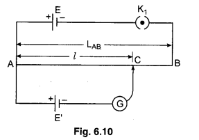
Principle : Suppose AB is a resistance of uniform area of cross section and length LAB- If a standard cell of emf E and negligible internal resistance is connected across the ends of wire A and B with the help of connection wires of negligible resistance, then the potential difference across the wire will be E. Therefore potential gradient.
k = \(\frac{E}{L_{A B}}\) ……………. (1)
If we consider a point C at a distance l from A, then
VAC = kl ………….. (2)
Now if a cell of unknown emf E’ is connected between A and C as shown in the figure, then the deflection in galvanometer will depend on the fact that whether VAC > E’ or E’ > VAC. When VAC = E’, then galvanometer will show no deflection. This fact can be understood well with the help of following equivalent circuit between A and C. This is null position galvanometer.
E’ = VAC
or E’ = kl ………………… (3)
This is the principle of potentiometer.
If E’ > E, then galvanometer will show the deflection in one direction only. In this situation the measurement of E’ is not possible.
If the resistance of potentiometer wire is RAB and the current is I then from the ohm’s law
E = IRAB ……………… (4)
From the equation (1)
k = \(\frac{I R_{A B}}{L_{A B}}\)
Let \(\frac{R_{A B}}{L_{A B}}\) = Density of wire is represented by the ρ
∴ k = ρI ……………… (5)
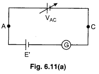
The circuit diagram for potential gradient
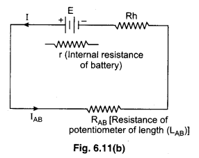
The potential gradient
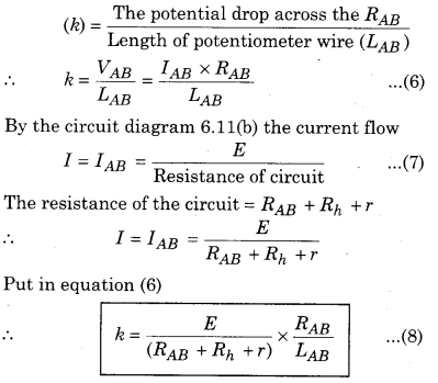
Value of potential gradient under different conditions : .
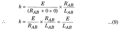
Case-1 : When only the battery of negligible internal resistance is connected to potentiometer.
∴ r = 0 and Rh = 0
From the equation (8)
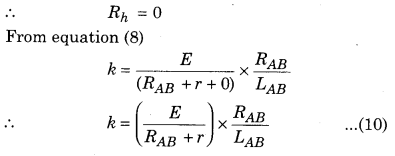
Case-2: When the battery of internal resistance (r) is connected to the potentiometer
Case-3: When a some other resistance or rheostat of resistance (Rh) is connected in series with the battery in the circuit of potentiometer. Then the potential gradient is calculated by equation (8).
k = \(\left(\frac{E}{R_{A B}+r+R_{h}}\right) \times \frac{R_{A B}}{L_{A B}}\)
Factors effecting the value of potential gradient:
From the equation (5)
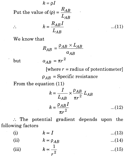
Question 5.
What is standardisation of potentiometer? Write the process of it and draw the necessary diagram.
Answer:
Standardisation of Potentiometer
For the potentiometer process of finding practical value of potential gradient is called standardisation of potentiometer.
For this process, a standard cell of known emf is required which is connected in secondary circuit as shown in figure (6.12).
Standard cell is a type of cell whose emf remains contant for long time. Cadmium cell or Daniel cell is used as standard cell. Its emf is 1.0186 V and 1.08 V at 20° C respectively.
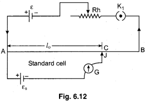
For finding potential gradient from standard cell, we slide jockey on wire and find out the balancing length where zero deflection is obtained in galvanometer. If the emf of standard cell is es then from the principle of potentiometer.
εs = kxl0
k = \(\frac{\varepsilon_{s}}{l_{0}}\) ……………… (1)
Question 6.
What is the sensitivity of potentiometer, how can it be increased?
Answer:
Sensitivity of Potentiometer
A potentiometer is sensitive if :
- It is capable of measuring very small potential difference.
- It shows a significant change in balancing length for a small change in the potential difference being measured. The sensitivity of a potentiometer depends upon the potential gradient along the wire. Smaller the potential gradient, greater will be the sensitivity of the Potentiometer.
The sensitivity of potentiometer can be increased by reducing the potential gradient. This can be done in two ways :
- For a given potential difference, the sensivity can be increased by the increasing the length of the potentiometer wire.
- For a potentiometer wire of fixed length, the potential gradient can be decreased by reducing the current in the circuit with the help of a rheostat. When in primary circuit current decreases then potential difference across the wire decreases so that without changing in primary circuit for reducing potential gradient the total length of the wire increases.
Graph between V and L
∵ The slope of graphical line
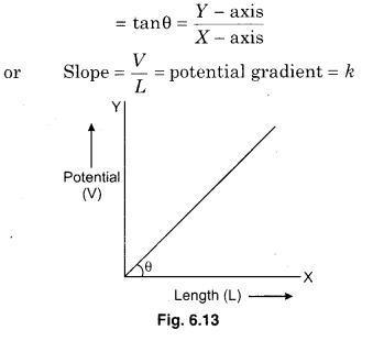
Question 7.
For comparing the emfs of the two primary cells by potentiometer draw the circuit diagram and deduce the formula.
Answer:
Comparison of Electromotive Forces of Two Primary Cells
Suppose we have to compare e.m.f. of two primary cells E1 and E2 with the help of potentiometer. For this purpose we prepare the circuit diagram as figure 6.15.
First of all we press key K1 and find out the balancing length l1 for cell E1. If k be the potential gradient of potentiometer wire, then
E1 = kl1 …………….. (1)
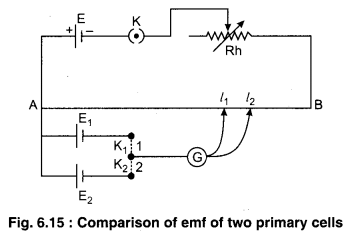
Now the key K1 is removed and K2 is fitted, then if l2 be the new balancing length, then
E2 = kl2 …………….. (2)
From equations (1) and (2), we have
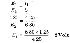
\(\frac{E_{1}}{E_{2}}=\frac{l_{1}}{l_{2}}\) ……………. (3)
Question 8.
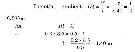
Standard cell of 1.2 V is balanced at the length of 2.40 m in potentiometer. Find out the balancing length for the potential difference across 3.5 Ω resistance where 0.2 A current is flowing through it, also find out potential gradient.
[x = 0.5V/m, l = 1.40 m]
Answer:
Question 9.
The real value of emf of cell or potential difference across resistance can not be measured by voltmeter, why? How real value can be measured by potentiometer?
Answer:
Potentiometer is a device which does not draw any current from the circuit and still measures the potential difference.
Question 10.
Why should we get the null point in the middle of the meter bridge wire? Explain.
Answer:
The metre bridge is most sensitive when the four resistances forming the Wheatstone’s bridge are equal. This is possible only if the balance point is somewhere near the middle of the wire.
Question 11.
Why should the current be not passed through potentiometer wire for a long time?
Answer:
This will heat up the potentiometer wire and will change its resistance. Potential drop per unit length of the wire will be also changed.
Question 12.
Why the value of current remain constant in primary circuit? Explain.
Answer:
On changing the current, the potential gradient will change and due to this error occurs is measurement.
Question 13.
Write the two precautions for using potentiometer.
Answer:
Precautions with Potentiometer
- emf of the cell connecting in primary circuit must be more than or equal to the emf of the cell of secondary circuit otherwise zero deflection can not be obtained.
- All the high potential points or positive terminals should be connected at A
- Balancing length should be calculated from A
- Area of cross-section of the wire should be uniform otherwise potential gradient will not be constant.
- Current should not be passing through potentiometer wire for a long time otherwise this will heat up the wire and will change its resistance and hence potential gradient will also changed.
Question 14.
What is the calibration of voltmeter by potentiometer. Draw the necessary circuit diagram.
Answer:
Calibration of Voltmeter
Observations measured from voltmeter is errorful due to different reasons :
(i) In built mechanical error,
(ii) Parallex error,
(iii) Unsymmetricity in the spring of voltmeter etc. Potentiometer can increase precise value of potential difference.
Checking the errors of observations of voltmeter by potentiometer is known as Calibration of Voltmeter.
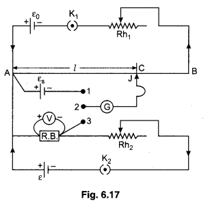
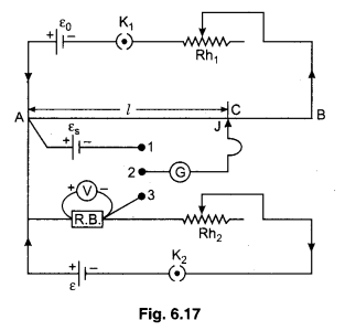
In figure 6.17 necessary circuit diagram is shown for calibration of voltmeter. Primary circuit is usually connected as section before.
In secondary circuit positive terminal of standard cell is connected at point A (high potential end) while negative terminal is connected with the terminal 1 of two way key. In this circuit other cell ε, rheostat Rh2, key K2 and resistance box (R.B.) is connected in series as shown in figure. The high potential end of R.B. is connected at A while lower potential end is connected at the terminal 3 of two way key. The voltmeter which is to be calibrated should be connected across the ends of R.B. The middle terminal of two way key is connected with the one end of galvanometer (G) and other end of (G) is connected with jockey.
Working : Firstly we completed the primary circuit and insert the plug between terminal 1 and 2 and by the help of jockey finding balancing length l0for the standard cell εs
\(\varepsilon_{s}=k l_{0} \quad \text { or } \quad k=\frac{\varepsilon_{s}}{l_{0}}\) …………….. (1)
k is potential gradient.
By the standardisation of cell, then find out k.
Now eliminate the plug between 1 and 2 and insert it between 2 and 3. Now key K2 be closed and suitable resistance out from R.B. By the help of Rh2 necessary current pass through the resistance and takes the deflection in voltmeter, which is V. It is errorful observation, corresponding to V. Find out the real value of potential difference by potentiometer. Find the balancing length l2. Now by the principle of potentiometer the real value of potential difference
V’ = kl2
V’ = \(\left(\frac{\varepsilon_{s}}{l_{0}}\right)\)l2 ………… (2)
Error in the observation of voltmeter
ΔV = V – V’
By the help of R.B. and Rh2, observe different values of voltmeter and for it find corresponding values of potential difference by potentiometer. Now taking difference of V (observations of voltmeter) and V’ (potential difference by potentiometer) we can find error in it
ΔV = V – V’
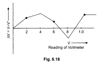
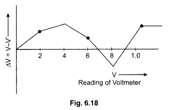
Calibration Curve : A graph is plotted between the readings of voltmeter and the corresponding errors. This graph is called calibration curve of the voltmeter. The graph has been no definite shape. The any graph of calibration is shown in figure 6.18.
Question 15.
Draw the necessary diagram for measuring small resistance by potentiometer?
Answer.
Measurement of Small Resistance
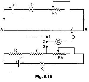
In figure 6.16 necessary circuit is shown.
Primary circuit is as usual. In secondary circuit, unknown small resistance r, known resistance R, rheostat Rh, key K2 and emf ε’ all are connected in series. Higher potential end of R, connects at point A which has higher potential, while lower potential end of R and r connects with the ends 1 and 3 of two way key. Terminal 2 of two way key connects with galvanometer end. Galvanometer also connects with jockey.
Working : Key K1 is closed, key K2 is also closed, now plug is inserted between terminal 1 and 2
of two way key. Now find out potential difference across resistance R by potentiometer. If I current flowing through secondary circuit, potential difference V across the ends of resistance R and the balancing length is l1 for V.
By the principle of potentiometer
V = kl1 ………….. (1)
but V = IR (by Ohm’s law)
IR = kl1 ………… (2)
Eliminate the plug between 1 and 2 and insert it between 2 and 3. Now R and r connect in series. Current I remains same in this circuit also now the potential difference across the ends of the (R + r) is V1 and balancing length for it is l2.
Putting the values l1, l2 and R, then internal resistance of primary cell (r) can be determined.
RBSE Class 12 Physics Chapter 6 Long Answer Type Questions
Question 1.
Give statements of Kirchhoff s junction and loop laws. Find out the balance condition of Wheatstone’s bridge with the help of these laws.
Answer:
“In an electric circuit, the algebraic sum of current at any junction point must be zero.”
i. e., ΣI = 0
The sum of currents entering a junction is equal to the sum of currents leaving out at the junction. This law is called Kirchhoff s First Law or Junction Law.
It is based on the law of Conservation of Charge. When currents in a circuit are steady, charges can not accumulate at any junction. So whatever charge flows towards the junction in any time interval, an equal charge must flow away from that junction in the same time interval.

In figure (6.1) at junction O,
I1 + I2 – I3 – I4 + I5 = 0
or I1 + I2 + I5 = I3 + I4 ………………. (1)
In figure (6.1) the currents flowing towards the junction are taken as positive and current flowing away from the junction are taken as negative.
Kirchhoff’s Second Law or Loop Law
This law is applicable for closed electrical circuit. The algebraic sum of the potential in a closed loop must be zero.
i.e., ΣV = 0 …………… (1)
The algebraic sum of the emfs in any loop of a circuit is equal to the sum of the voltages across the resistances.
ΣE = ΣIR ………….. (2)
Sign convention for applying Loop Rule
1. The product of current and resistance (IR) is taken as positive if the resistor is traversed in the same direction of assumed current. The product of current and resistance (IR) is taken as negative if the resistor is traversed in the opposite direction of assumed current.

In loop we can move from A to B then the product of IR take as positive VAB = +IR. [In the direction of current]
In a loop we can move from B to A then the product of IR take as negative.
∴ VBA = -IR [Opposite direction of current]
2. When we move from B to A then E is taken positive (+). When we move from AtoB, then Eis taken negative (-).
Loop law can be understood by the figure 6.4.
In the given figure for point d by the Junction Law, current flowing through the resistance R% will be
I3 = I1 + I2 …………… (3)
In the loop adcba by the Kirchhoff s Loop Law.
I1R1 – I2R2 = ε1 – ε2
or I2R2 = I2R2 = ε2 – ε1 ………… (4)
In the loop defcd by the Loop Law
I3R3 + I2R2 = ε2 …………….. (5)
By solving equations (3), (4) and (5) we can find out electric currents in different branches as well as we can find potential differences across the resistances.
Construction : The construction of Wheatstone’s bridge is shown in following diagram (figure 6.5) in which a quadrilateral ABCD is prepared by
connecting four resistances P, Q, R and S. A cell is connected between the points A and C through key K1 which is known as battery key and a galvanometer between the point B and D through another key K2 which is known as galvanometer key. If on pressing the key K1 and K2, there is no deflection in galvanometer, then the bridge is said to be balanced condition. In this situation the relation between all the resistances is given by :
\(\frac{P}{Q}=\frac{R}{S}\)
Principle of Wheatstone Bridge and Condition of Balance
When battery key K1 is pressed, then main current I starts flowing in the circuit. At junction A this current splits in two parts I1 and I2 as shown in figure 6.6. These currents I2 and I2 again obtain two paths at junctions B and D respectively. Now following three situations are possible :
(i) When VB > VD. then current I2 passes as such through resistance S but current I1 splits in two parts at junction B, one part Ig passes through galvanometer showing deflection in one direction while rest current (I1 – Ig) passes through Q.
(ii) When VB < VD. then opposite situation to previous situation (i) is observed i.e. .current I2 splits in two parts at D. Now the current Ig produces deflection in galvanometer in opposite direction to previous deflection.
(iii) When VB = VD , then no current passes through galvanometer i.e.. galvanometer shows no deflection because now I g = 0. This situation is said to be balance condition of Wheatstone bridge. It is clear that current is flowing in the circuit but there is no effect of current on galvanometer arm which resembles with the bridge on a river. This is why this circuit is called ‘Bridge circuit’ Thus in balanced condition.
Therefore, “it is clear that in balanced situation of the bridge, ratio of resistances of any two corresponding arms of quadrilateral ABCD is equal to ratio of two remaining corresponding arms”.
From equation (3).
S = \(\frac{Q}{P} \times R\)
Thus, by determining the balanced situation, unknown resistance can be determined.
The arms of Wheatstone bridge are known as particulars names given below :
(i) P and Q are called ratio arms.
(ii) R is called variable resistance arm.
(iii) S is called unknown resistance arm.
Question 2.
What is the meter bridge? On which principle does it work? Explaining its construction obtain the expression for determining unknown resistance with the help of meter bridge. Give necessary diagram also.
Answer:
Meter Bridge
It is the simplest practical application of the Wheatstone bridge that is used to measure an unknown resistance.
Construction : It consists of usually one meter long Manganin or constant on wire of uniform cross-sectional area, stretched along a meter scale fixed over a wooden board and with its two ends soldered to two L- shaped thick copper strips M and N. Between these two copper strips, another copper strip I is fixed so as to provide two gaps ab and a1b1. A resistance box R.B. is connected in the gap ab and the R.B. G
unknown resistance S is connected to the gap ab. and the

unknown resistance S is connected to the gap a1b1. A source of emf e is connected across AC. A movable jockey and a galvanometer are connected at BD as shown in figure.
Working : After taking out a suitable resistance R from the resistance box, we touches the jockey at point A and C and observe opposite deflection in galvanometer. If galvanometer shows deflection in one direction then we change the value of known resistance until galvanometer shows opposite deflection.
Now the jockey is moved along the wire AC till there is no deflection in the galvanometer. This is the balanced condition of the Wheatstone bridge. If P and Q are the resistances of the parts AB and BC of the wire, then for the balanced condition of the bridge we have
\(\frac{P}{Q}=\frac{R}{S}\) ……………….. (1)
If resistance of unit length of the wire is \(\sigma \frac{\mathrm{ohm}}{\mathrm{cm}}\) and the balance point occurs at l cm from A then the length of part BC will be (100 – l) cm.
P = Resistance of wire of AB part = σl …………. (2)
Q = Resistance of wire of BC part = σ (100 – l) ……………… (3)
In equation (1) putting the value P and Q
Knowing l and R, unknown resistance can be determined.
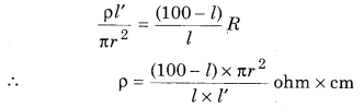
The formula of determination of specific resistance of unknown resistannce (S)
We know that
Unknown resistance (S) = \(\rho \frac{l^{\prime}}{A}\)
Where l’ = Length of unknown resistance
A = Area of cross section = πr2
From equation (4)
Limitations of Meter Bridge :
- Copper strips have their own resistances but in the calculation of meter bridge formula we neglect this resistance so that our results are errorful. For minimising this error, at time of performing experiment we should calculate unknown resistance by interchanging the position of unknown resistance and known resistance. In this process we take average value of obesrvations by which error can be minimised.
- The resistances of endpoints affect the sensitivity of the meter bridge. To nulify, this effect Carey-Foster s bridge is used.
- Current should not flow for long time through the wire otherwise wire will heat up and the resistance of wire will be changed.
- Jockey should not slide tightly on resistance wire otherwise it’s cross-section area will change. That is why the resistance of wire will be changed.
Question 3.
What do you understand by internal resistance of a cell? Establish the relation for determining the internal resistance of a cell by potentiometer.
Answer.
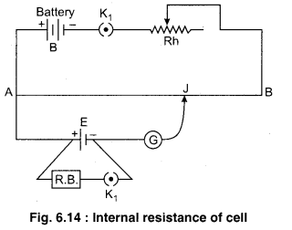
Determination of Internal Resistance of Primary Cell
To determine the internal resistance of a cell, we prepare a circuit as shown in the figure 6.15. Primary circuit is prepared by connecting a battery, a key K and a rheostat in series with potentiometer wire AB. In secondary circuit the cell E of unknown internal resistance r and a resistance box are connected with outer terminals of a two way key. The middle terminal of this key is connected with galvanometer and second terminal of galvanometer to jockey which can move on potentiometer wire.The whole practical is conducted in following steps :
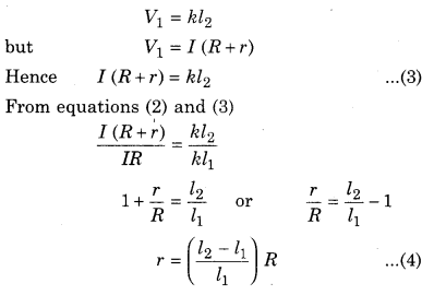
(i) First of all the key K1 is closed then the cell E is only is working condition and no current flow through the external resistance in a secondary circuit. So, potentiometer measured the emf of cell. Let the balance point is obtained at the length l1 from the point A If k be the potential gradient.
∴ emf of cell = Potential gradient × Length
E = kl1 …………… (1)
(ii) Now key K2 also is pressed and some appropriate resistance R is applied by resistance box. In this situation the balance point is obtained at length of l2 corresponding to terminal voltage V, therefore
V = kl2
Since the internal resistance is obtained by following relation :
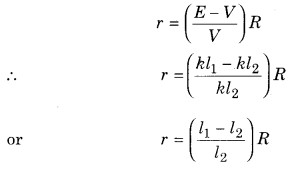
Substituting the values of l1, l2 and R we can get the internal resistance (r) of the cell.
Question 4.
What is meaning of calibration of voltmeter and ammeter. Explain the method of calibration of voltmeter and ammeter with the help of potentiometer. Make the required circuit diagram and draw the calibration curve.
Answer:
Calibration of Voltmeter
Observations measured from voltmeter is errorful due to different reasons :
(i) In built mechanical error, (ii) Parallex error,
(iii) Unsymmetricity in the spring of voltmeter etc. Potentiometer can increase precise value of potential difference.
Checking the errors of observations of voltmeter by potentiometer is known as Calibration of Voltmeter.
In figure 6.17 necessary circuit diagram is shown for calibration of voltmeter. Primary circuit is usually connected as section before.
In secondary circuit positive terminal of standard cell is connected at point A (high potential end) while negative terminal is connected with the terminal 1 of two way key. In this circuit other cell ε, rheostat Rh2, key K2 and resistance box (R.B.) is connected in series as shown in figure. The high potential end of R.B. is connected at A while lower potential end is connected at the terminal 3 of two way key. The voltmeter which is to be calibrated should be connected across the ends of R.B. The middle terminal of two way key is connected with the one end of galvanometer (G) and other end of (G) is connected with jockey.
Working : Firstly we completed the primary circuit and insert the plug between terminal 1 and 2 and by the help of jockey finding balancing length l0for the standard cell εs
\(\varepsilon_{s}=k l_{0} \quad \text { or } \quad k=\frac{\varepsilon_{s}}{l_{0}}\) …………….. (1)
k is potential gradient.
By the standardisation of cell, then find out k.
Now eliminate the plug between 1 and 2 and insert it between 2 and 3. Now key K2 be closed and suitable resistance out from R.B. By the help of Rh2 necessary current pass through the resistance and takes the deflection in voltmeter, which is V. It is errorful observation, corresponding to V. Find out the real value of potential difference by potentiometer. Find the balancing length l2. Now by the principle of potentiometer the real value of potential difference
V’ = kl2
V’ = \(\left(\frac{\varepsilon_{s}}{l_{0}}\right)\)l2 ………… (2)
Error in the observation of voltmeter
ΔV = V – V’
By the help of R.B. and Rh2, observe different values of voltmeter and for it find corresponding values of potential difference by potentiometer. Now taking difference of V (observations of voltmeter) and V’ (potential difference by potentiometer) we can find error in it
ΔV = V – V’
Calibration Curve : A graph is plotted between the readings of voltmeter and the corresponding errors. This graph is called calibration curve of the voltmeter. The graph has been no definite shape. The any graph of calibration is shown in figure 6.18.
Calibration of Ammeter
Checking of the errors of observations of electric current by ammeter by potentiometer is known as calibration of ammeter.
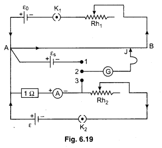
Circuit : For calibration of ammeter necessary circuit diagram is shown in figure 6.19.
Primary circuit is usually connected. In secondary circuit positive terminal of standard cell εs is connected at point A (high potential end) while negative terminal is connected with the terminal 1 of two-way key. In this circuit other cell ε1 rheostat Rh2, key K2 and 1 Ω coil and ammeter are connected in series as shown in figure.
Working : Firstly we complete the primary circuit and insert the plug between terminal 1 and 2 and by the help of jockey find balancing length l0 for the standard cell εs
εs = kl0
or k = \(\frac{\varepsilon_{s}}{l_{0}}\) ………………… (1)
k is potential gradient. By the standardisation of cell find out the k. Now eliminating the plug between the terminals 1 and 2 and inserting it between 2 and 3. Now key K2 is closed. By the help of Rh2 necessary current pass through the 1 Ω coil and takes the deflection in ammeter, which is I. It is errorful observation.
By Ohm’s law, current flowing through 1 Ω resistance is equal to the potential difference across the ends of the 1 Ω coil. Obtain balancing length l2 for the potential difference across the ends of the 1 Ω coil. Obtain balancing length l2 for the potential difference V’ which is across the ends of the coil.
V’ = kl2 but V’ = I’R, R = 1 Ω
I’ = kl2
I’ = \(\left(\frac{\varepsilon_{s}}{l_{0}}\right)\) l2 …(2)
I’ is the real value of current which is measured by the potentiometer. Now obtain the error in current observed by ammeter as ΔI.
ΔI = I – I’
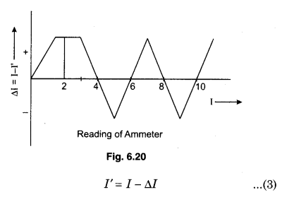
For different readings of ammeter obtain corresponding real current by potentiometer then the corresponding error will be I – I’. Plotting the curve between I – I’ and I which is called calibrated curve of ammeter. Zig-zag curve is obtained as shown in figure 6.20.
We can find real reading by calibrated curve
Question 5.
What is potentiometer? Explain its principle. Describe the method of determining a small resistance by potentiometer. Make necessary diagram also.
Answer:
Principle of Potentiometer
Potentiometer : Potentiometer is a apparatus with help of which the e.m.f. of a cell and potential difference can be measured accurately.
Principle : Suppose AB is a resistance of uniform area of cross section and length LAB- If a standard cell of emf E and negligible internal resistance is connected across the ends of wire A and B with the help of connection wires of negligible resistance, then the potential difference across the wire will be E. Therefore potential gradient.
k = \(\frac{E}{L_{A B}}\) ……………. (1)
If we consider a point C at a distance l from A, then
VAC = kl ………….. (2)
Now if a cell of unknown emf E’ is connected between A and C as shown in the figure, then the deflection in galvanometer will depend on the fact that whether VAC > E’ or E’ > VAC. When VAC = E’, then galvanometer will show no deflection. This fact can be understood well with the help of following equivalent circuit between A and C. This is null position galvanometer.
E’ = VAC
or E’ = kl ………………… (3)
This is the principle of potentiometer.
If E’ > E, then galvanometer will show the deflection in one direction only. In this situation the measurement of E’ is not possible.
If the resistance of potentiometer wire is RAB and the current is I then from the ohm’s law
E = IRAB ……………… (4)
From the equation (1)
k = \(\frac{I R_{A B}}{L_{A B}}\)
Let \(\frac{R_{A B}}{L_{A B}}\) = Density of wire is represented by the ρ
∴ k = ρI ……………… (5)
The circuit diagram for potential gradient
The potential gradient
Value of potential gradient under different conditions : .
Case-1 : When only the battery of negligible internal resistance is connected to potentiometer.
∴ r = 0 and Rh = 0
From the equation (8)
Case-2: When the battery of internal resistance (r) is connected to the potentiometer
Case-3: When a some other resistance or rheostat of resistance (Rh) is connected in series with the battery in the circuit of potentiometer. Then the potential gradient is calculated by equation (8).
k = \(=\left(\frac{E}{R_{A B}+r+R_{h}}\right) \times \frac{R_{A B}}{L_{A B}}\)
Factors effecting the value of potential gradient:
From the equation (5)
Measurement of Small Resistance
In figure 6.16 necessary circuit is shown.
Primary circuit is as usual. In secondary circuit, unknown small resistance r, known resistance R, rheostat Rh, key K2 and emf ε’ all are connected in series. Higher potential end of R, connects at point A which has higher potential, while lower potential end of R and r connects with the ends 1 and 3 of two way key. Terminal 2 of two way key connects with galvanometer end. Galvanometer also connects with jockey.
Working : Key K1 is closed, key K2 is also closed, now plug is inserted between terminal 1 and 2
of two way key. Now find out potential difference across resistance R by potentiometer. If I current flowing through secondary circuit, potential difference V across the ends of resistance R and the balancing length is l1 for V.
By the principle of potentiometer
V = kl1 ………….. (1)
but V = IR (by Ohm’s law)
IR = kl1 ………… (2)
Eliminate the plug between 1 and 2 and insert it between 2 and 3. Now R and r connect in series. Current I remains same in this circuit also now the potential difference across the ends of the (R + r) is V1 and balancing length for it is l2.
Putting the values l1, l2 and R, then internal resistance of primary cell (r) can be determined.
RBSE Class 12 Physics Chapter 6 Numerical Questions
Question 1.
Find out equivalent resistance between a and b.
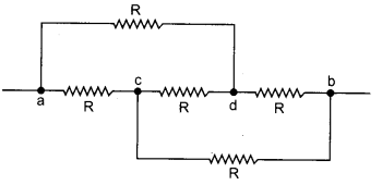
Solution:
Arranging the circuit :
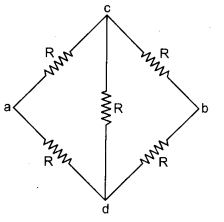
This circuit follows a Wheatstone bridge so arm cd does not work.
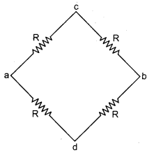
Adding resistances of path acb in series
R2 = R + R = 2R
Adding resistances of path adb in series
R2 = R + R = 2R
Adding R1 and R2 in parallel
\(R^{\prime}=\frac{R_{1} \times R_{2}}{R_{1}+R_{2}}=\frac{2 R \times 2 R}{4 R}=R \Omega\)
Question 2.
Meter bridge is in balanced state shown in figure. Resistance of per unit length of the meter bridge wire is 1 Ω/cm. Find unknown resistance X and find electric current flowing through it.
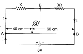
Solution:
According to condition of metre bridge
Question 3.
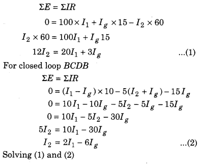
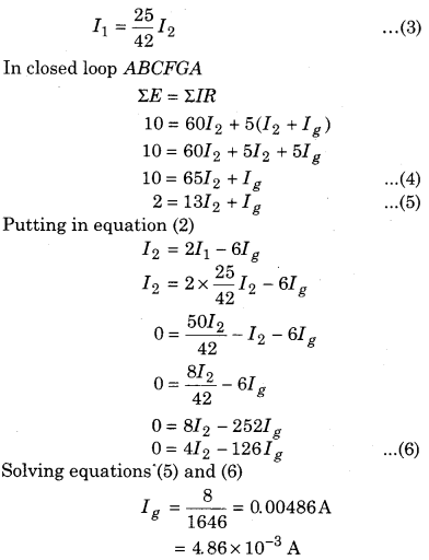
Resistances of four sides of Wheatstone bridge is AB = 100 Ω, BC = 10 Ω, CD = 5 Ω and DA = 60 Ω. Galvanometer of 15 Ω resistance is connected between BD. Find the current flowing through the galvanometer. Potential difference between A and C is 10 V.
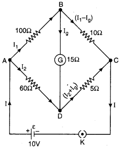
Solution:
For closed mesh ABDA
Question 4.
What should be the resistance R shown in figure so that galvanometer shows zero deflection?
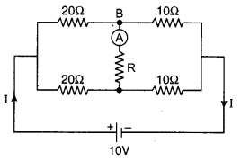
Solution:
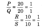
This circuit represents Wheatstone bridge.
∴ Resistance in arm AS will not work.
∴ Current flowing through R = 0
Hence, for the any value of resistance R, the current flowing by the ammeter will be zero.
Question 5.
Length of potentiometer wire is L. In primary circuit battery of 2.5 V and 10 ft resistance is combined in series. Balance length
is \(\frac{L}{2}\) for emf 1.0 Ω. If the resistance of primary circuit becomes double then what is the new balance length?
Solution:
Length of wire = L Potential (V) = 2.5 (V)
Let a resistance of R1 ohm is placed in series with battery, then current
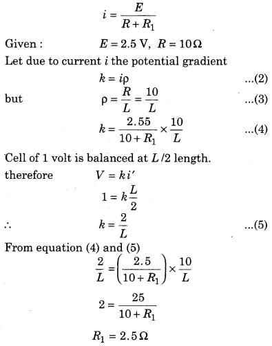
When we double the resistance R1, connected in series with potentiometer then total resistance (R’) = R + 2R1
R’ = 10 + 5 = 15 Ω
In this condition if current in potentiometer is i, then
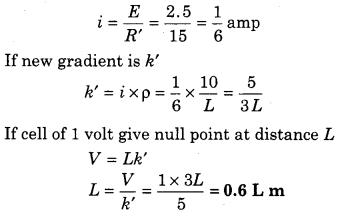
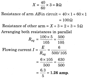
Question 6.
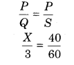
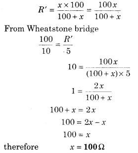
The Wheatstone bridge is shown in figure. What should be the value of X so that Wheatstone bridge will be balanced?
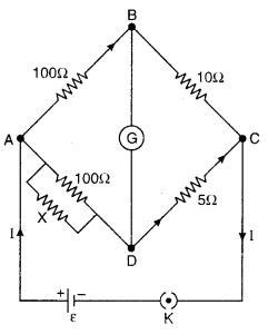
Solution:
Equivalent resistance of X Ω and 100 Ω in parallel
Question 7.
Standard cell of 1.1 V emf is balanced at 0.88 m length of the potentiometer wire. Potential difference across 1 Ω resistance is balanced at 0.20 m length of the wire of potentiometer. If the reading of ammeter is 0.20 A, then find out the error in the measurement of ammeter.
Solution:
From principle of potentiometer,
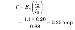
Reading in ammeter (I) = 0.20 amp
Error in the measurement of current (ΔI) = I – I’
= 0.20 – 0.25 = -0.05 amp
Question 8.
In the experiment of potentiometer, for 1.25 V emf balance length is obtained at 4.25 m. For an another cell it is obtained at 6.80 m. Find out the emf of another cell.
Solution:
From potentiometer condition
Question 9.
The resistance of 10 m potentiometer wire is 1 Ω/m. Battery accumulator of 2.2 V and negligible internal resistance and high resistance connecting in series with the wire. For achieving 2.2 mV/m potential gradient how much high resistance will have to take?
Solution:
Length of potentiometer wire
LAB = 10m
Density of resistance of wire = 1 Ω/m
Resistance of potentiometer
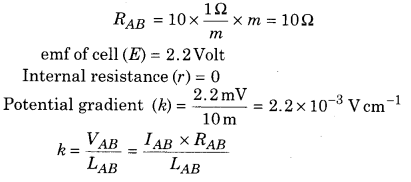
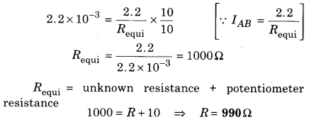
Question 10.
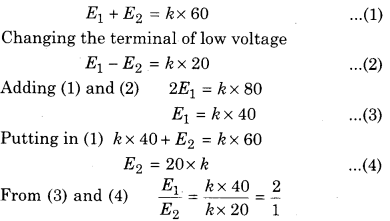
In potentiometer experiment two cell of emf of ε1 and ε2 combined in series (ε1> ε2) for it balance length obtained at 60 cm. If the polarity of the cell having lower emf is then the balance length achieves at 20 cm for the combination. Find out the ratio of emf’s ε1 and ε2
Solution:
Let gradient of potentiometer is k