Rajasthan Board RBSE Class 12 Physics Chapter 7 Magnetic Effects of Electric Current
RBSE Class 12 Physics Chapter 7 Text Book Exercise with Answers
RBSE Class 12 Physics Chapter 7 Multiple Choice Type Questions
Question 1.
Any charged particle which is moving with a uniform speed and it generates :
(a) Only electric field
(b) Only magnetic field
(c) Both electric and magnetic field
(d) Electromagnetic waves with electric and magnetic field
Answer:
(c) Both electric and magnetic field
When an charged particle is moving with uniform speed produces both electric field and magnetic field.
Question 2.
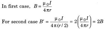
The magnetic field B is from a long straight current carrying conductor wire at a distance r. If the current flowing in the wire is constant then what would be the value of the magnetic field at a distance \(\frac{r}{2}\)?
(a) 2B
(b) \(\frac{B}{2}\)
(c) B
(d) \(\frac{B}{4}\)
Answer:
(a) 2B
Question 3.
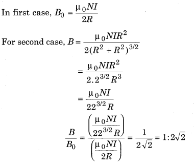
The magnetic field B0 is generated at the centre of a circular current carrying coil. On the axial point of this coil, the magnetic field at a distance equal to the radius is B. Then what is the value of \(\frac{B}{B_{0}}\)?
![]()
Answer:
(b)
Question 4.
Helmholtz coils are used :
(a) to generate uniform magnetic field
(b) to measure electric current
(c) to measure magnetic field
(d) to know the direction of the electric current
Answer:
(a) to generate uniform magnetic field
Helmholtz coils are used to generate uniform magnetic field.
Question 5.
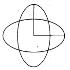
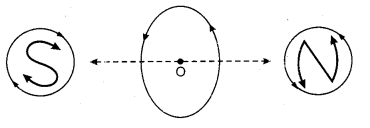
As shown in the figure same current is flowing in the two similar coils. The centres of the coil coincide and the planes are perpendicular. If B is the magnetic field due to a coil then what would be the resultant magnetic field at coinciding center?
(a) Zero
(b) 2B
(c) \(\frac{B}{\sqrt{2}}\)
(d) \(\sqrt{2} B\)
Answer:
(d) \(\sqrt{2} B\)
Resultant magnetic field at common centre
B = \(\sqrt{\left(B_{1}^{2}+B_{2}^{2}\right)}=\sqrt{B^{2}+B^{2}}=\sqrt{2} B\)
Question 6.
On which particle given below maximum force is acting when they are moving with same velocity in a uniform magnetic field projected perpendicular,
(a) 1e0
(b) 1H1
(c) 2He4
(d) 3Li7
Answer:
(d) 3Li7
Maximum force will be imposed on 3Li7
Question 7.
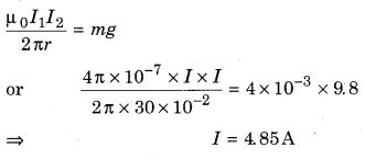
The distance between the supply wires of an electric-mains is 12 cm. These wires experience 4 mg weight per unit length. Current flowing in both the wires will be :
(a) zero
(b) 4.85 A
(c) 4.85 mA
(d) 4.85 × 10⁻⁴ A
Answer:
(b) 4.85 A
Question 8.
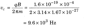
A proton of energy 100 eV is moving perpendicular to a magnetic field of 10~4T. The cyclotron frequency of the proton in radian/sec.:
(a) 2.80 × 10⁶
(b) 9.6 × 10³
(c) 5.6 × 10⁶
(d) 1.76 × 10⁶
Answer:
(b) 9.6 × 10³
Question 9.
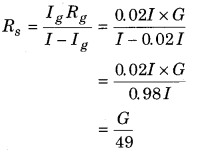
A galvanometer of resistance G requires 2% of main current for full scale deflection the shut resistance value will be :
(a) \(\frac{G}{50}\)
(b) \(\frac{G}{49}\)
(c) 49 G
(d) 50G
Answer:
(b) \(\frac{G}{49}\)
Question 10.
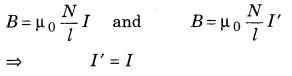
The magnetic field B is generated in a solenoid in which current I is flowing. If the length of the solenoid and number of turns are doubled then to get the same magnetic field how much current must be flowing?
(a) 2I
(b) I
(c) \(\frac{I}{2}\)
(d) \(\frac{I}{4}\)
Answer:
(b) I
Question 11.
The magnetic field inside a toroid is B. If n are the number of turns in unit length of the toroid is n and I current is flowing in the toroid then magnetic field outside the toroid will be :
(a) B
(b) \(\frac{B}{2}\)
(c) Zero
(d) 2B
Answer:
(c) Zero
There is no current flowing in external loop so B = 0
Question 12.
A pivoted coil galvanometer is converted into a voltmeter by:
(a) high resistance connected in series
(b) low resistance connected in series
(c) high resistance connected in parallel
(d) low resistance connected in parallel
Answer:
(a) high resistance connected in series
A high resistance is connected in series to convert a moving coil galvanometer into voltmeter.
Question 13.
The resistance of an ideal voltmeter and an ideal ammeter should be:
(a) zero and infinite respectively
(b) infinite and zero respectively
(c) both should be zero
(d) both should be infinite
Answer:
(b) infinite and zero respectively
The resistance of an ideal voltmeter should be infinite and resistance of an ideal ammeter should be zero.
RBSE Class 12 Physics Chapter 7 Very Short Answer Type Questions
Question 1.
Write the various sources name to generate the magnetic field.
Answer:
Various sources to produce magnetic field are :
magnet, current carrying conductor, moving charge, change in electric field.
Question 2.
Write the dimensional formula and unit of magnetic field.
Answer:
Dimension of magnetic field = [M1L0T-2A-1]
Unit- Tesla (7)
Question 3.
Which fields are generated by moving charge?
Answer:
Moving charges produce both electric and magnetic field.
Question 4.
A charge q enters in a perpendicular direction of \(\overrightarrow{\mathrm{B}}\) with \(\overrightarrow{\mathrm{v}}\) velocity. What would be the force on this charge and what would be the path of the particle?
Answer:
Force acting on charge
F = q \(\overrightarrow{(v} \times \vec{B} )\)
\(| \vec{F} \rceil\) = qvBsin 90°= qvB
The path of the particle will be circular.
Question 5.
Define 1 ampere current in International Unit System.
Answer:
One ampere current is defined as the constant current which is maintained in two straight parallel conductors of infinite length at a distance 1 metre apart placed in vacuum of negligible circular cross section, would produce between these conductors a force equal to 2 × 10⁻⁷ N/m of length.
Question 6.
What will be the direction of the magnetic field if a proton is moving vertically upwards and the magnetic force acting on it is in a horizontal plane towards the north?
Answer:
According to Fleming’s left hand rule in horizontal plane towards west.
Question 7.
A charged particle does uniform motion in a uniform magnetic field then how would be the path of the particle?
Answer:
Linear path.
Question 8.
On any circular coil a constant voltage battery is connected at the diameter ends. What would be the magnetic field at the centre of the coil?
Answer:
Magnetic field at the centre of the coil will be zero.
Question 9.
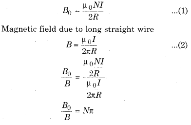
If a current carrying coil of radius R and having N turns is opened and made into a straight long wire. Then the magnetic field at a distance R would be how many times of the value of the centre of the coil?
Answer:
Magnetic field at centre
Question 10.
What is the distance between the points of inflexion in the Helmholtz coil?
Answer:
Equal to the radius of the coil.
Question 11.
Write the mathematical form of Ampere’s circuital law.
Answer:
\(\oint \overrightarrow{\mathrm{B}} \cdot \overrightarrow{\mathrm{d} l}=\mu_{0}\left(I_{c n}\right)\)
Questions 12.
In a long tube of copper having internal radius R, I current is flowing. Calculate the magnetic field inside the tube.
Answer:
Zero.
Question 13.
Why are the polar pieces of stable magnet used in a galvanometer made of concave shape?
Answer:
Pole pieces of permanent magnet are used in a galvanometer of concave shape to produce radial magnetic field.
Question 14.
How can the current sensitivity of a galvanometer be increased?
Answer:
By increasing the number of turns in the coil and taking soft iron core.
Question 15.
What will be the position of the magnetic field and the coil of a galvanometer when it is in equilibrium position?
Answer:
Plane of coil will be perpendicular to magnetic field.
Question 16.
Why is a cyclotron not used to accelerate low weight charged particles?
Answer:
When the energy of light charged particles is increased, their mass increases due to relativistic effect.
Question 17.
Which appliance would you prefer to generate uniform magnetic field?
Answer:
Helmholtz’s coil.
Question 18.
In any cyclotron how does the half time period of any particle in a dee is dependent on the radius of the path and speed of the particle?
Answer:
Time period remains constant.
∵ \(t=\frac{\pi m}{q B}\)
Question 19.
Write down the formula for necessary high resistance to convert a galvanometer into a voltmeter of desired range.
Answer:
R = \(\frac{V}{I_{g}}-G\)
Here, Ig = required current for full scale deflection. G is the resistance of the galvanometer and V is the range of voltmeter.
RBSE Class 12 Physics Chapter 7 Short Answer Type Questions
Question 1.
Write down the results of Oersted’s experiments.
Answer:
Conclusions from Oersted’s Experiment
The following conclusions were stated from Oersted’s experiment :
- When an electric current is passed through a conducting wire, then the magnetic field is produced around it.
- When the magnitude of electric current is increased, then the magnitude of magnetic field is also increased.
- The strength of the established magnetic field due to current carrying conductor depends upon the position of observation point from the wire. Relatively stronger magnetic field is produced near the wire while on increasing the distance of observation point from the wire, the magnetic field intensity goes on decreasing.
- If the direction of current passing through the wire is from south to north, the north pole of the magnetic field is deflected towards the west. If the direction of current is flowing from north to south, the north pole of the magnetic needle is deflected towards the east. So on changing the direction of the current in the wire, then the direction of magnetic field is also changed.
- The direction of magnetic field above and below the conducting wire is always opposite. In the coming discussion we would explain magnetic field. This is dependent on position and time both.
Question 2.
Define Biot-Savart’s law in vector form.
Answer.
Vector form of Biot-Savart’s law
Question 3.
Explain two rules for calculating the direction of the magnetic field.
Answer:
Direction of Magnetic Field
The direction of a magnetic field can be known by the following direction rules :
(i) SNOW Rule : SNOW rule states that if the current is flowing in an electric circuit from South to North direction and a magnetic compass is placed over the conducting wire, the needle of the compass deflects in the direction of West
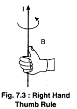
(ii) Right Hand Thumb Rule : According to this rule if you held the wire carrying current in your right hand so that the thumb indicate the direction of current then the curved fingers represent the direction of magnetic field (figure 7.3).
Question 4.
Any charged particle enters in a uniform magnetic field at an angle θ (where 0°< θ < 90°). How will be the path of the particle? Calculate its pitch.
Answer:
Motion of Charged Particle When 0°< θ < 90°.
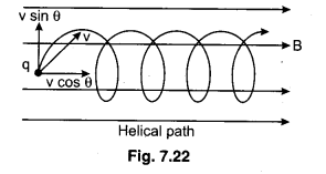
When a charged particle enters in the magnetic field at an angle θ other than 0° and 90°, then its velocity v can be resolved in two perpendicular components as under :
(i) v cosθ — along the magnetic field and
(ii) v sinθ — perpendicular to magnetic field.
Due to the component v cos θ. the path will be straight line while due to component v sinθ, the path will be circular. Hence the resultant path of the particle will become ‘Helical’ as shown in the figure (7.22).
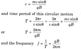
The radius of this helical path,
Pitch of the Helical Path : The distance travelled in one time period along the axis of the helical path is called the pitch of the path therefore,
Pitch = v cosθ × T
or pitch = v cosθ × \(\frac{2 \pi m}{q B}\)
or pitch = \(\frac{2 \pi m v \cos \theta}{q B}\)
Question 5.
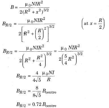
Calculate the magnetic field at a R distance \(\frac{R}{2}\) from the center and on the axis of a circular current carrying coil. Also calculate the relationship between magnetic field found and the magnetic field at the centre. Here R is the radius of the coil.
Answer:
Question 6.
Show how does a small circular current carrying loop behaves as a magnetic dipole?
Answer:
When current flows through a current carrying loop, then loop behaves as magnetic dipole or bar magnet. Or we may say one face is like magnetic south pole S and second face like north pole N. Face at which current is anticlockwise is north pole and face at which current is clockwise is called south pole.
Question 7.
What is the circulation of magnetic field? Explain.
Answer:
In a simplified form, circulation of current means that if field \(\vec{B}\) is directed along the tangent to every point on the perimeter L of a closed curve and its magnitude is constant along the curve. Then BL = µ0I
Question 8.
What is the difference in behaviour of a solenoid and magnetic dipole?
Answer:
- In solenoid the magnetic field lines are nearly parallel while outside bar magnet they are curved.
- Outside solenoid, magnetic field is nearly zero while in bar magnet it is along its length.
Question 9.
Calculate the magnetic force due to a current carrying conductor on the unit length of another parallel current carrying conductor.
Answer:
Magnetic Force Acting between Two Current Carrying Parallel Wires
We have studied that magnetic field is produced around the current carrying conductor and a magnetic force is experienced by a current carrying conductor situated in magnetic field. Therefore if two current conductors are placed near each both of them experience a magnetic force.
Suppose two long straight current carrying wires AB and CD having current I1 and I2 respectively are placed parallel to each other at a distance of r as shown in the diagram. Each wire is situated in magnetic field of other wire, therefore both of them will experience magnetic force.
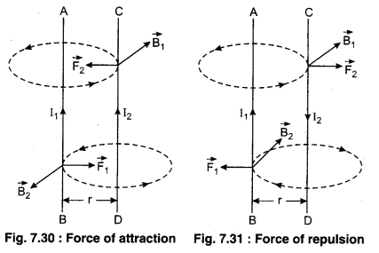
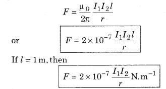
When the current in both wires is in same direction, then they will experience force of attraction between them and when the currents are in opposite directions, then they experience a force of repulsion between them. The directions of force can be decided by right hand rule (for magnetic field produced) and Fleming’s left hand rule (for force experienced). This force was calculated by applying Biot-Savart’s law and Lorentz’s force therefore this is also known as ‘Ampere’s law’. It can be explained as under : According to Biot-Savart’s law, the magnetic field produced by current I1 in the position of wire CD,
\(B_{1}=\frac{\mu_{0}}{2 \pi} \frac{I_{1}}{r}=\frac{\mu_{0}}{4 \pi} \frac{2 I_{1}}{r} \mathrm{NA}^{-1} \mathrm{m}^{-1}\)
According to Right Hand Palm Rule no.l, the direction of this magnetic field will be normal to plane of the paper inwards. Since wire CD is situated in this field at right angles to field, therefore force acting on CD,
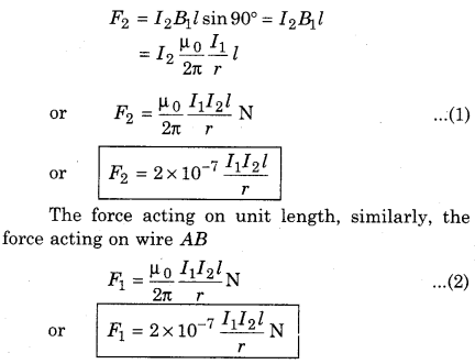
From equations (1) and (2), it is clear that
F1 = F2 = F
Thus, we can write, the magnetic force between two parallel current carrying wires,
Question 10.
Calculate the magnetic field at any point with the help of Ampere’s law inside a long current carrying cylindrical conductor.
Answer:
Magnetic Field due to Current Carrying Long Cylindrical Conductor :
Suppose in a cylindrical conductor of R radius has a current I flowing in it which is evenly distributed on the whole cross-sectional area. We have to calculate the magnetic field at a distance r perpendicular from this conductor. Due to symmetric distribution of the current it is assumed that the magnetic lines of the magnetic field B will be circular and in concentric circles whose centre will be at axis of the cylinder.
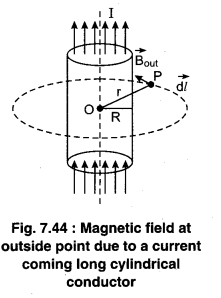
(i) When the point is outside the cylindrical conductor meaning r > R. As shown in the figure (7.44) we discuss on a circular closed path of radius r. On this path at every point the magnetic field is same (constant) and direction along the path. From Ampere’s law,
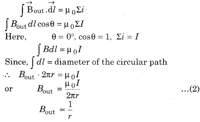
It is clear that the magnetic field at outside points due to a cylindrical conductor is inversely proportional to the distance.
(ii) When the point is positioned at the surface of the cylindrical conductor meaning r = R.
Keeping the value of r = R in equation (2)
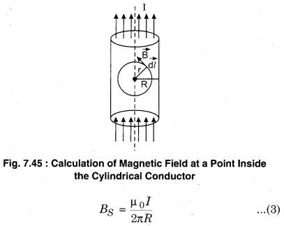
(iii) When the point is inside the cylindrical conductor meaning r < R. According to the figure (7.45) let us consider a cylindrical conductor inside which is a closed circular loop of radius r. From Ampere’s law
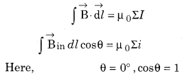
Here, the current Σi of the Amperinal loop is also the current of a loop of area nr2. Since the current is uniformly distributed.
∴ r(r < R) radius of the circular path or the current will be the ratio of the area of the circle and πr2 cross-sectional area of the conductor.
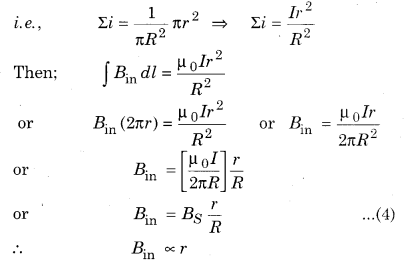
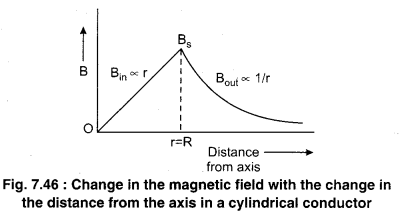
It is clear that the magnetic field inside a cylindrical conductor is directly proportional to the distance from the axis.
If r = 0 then B = 0
i.e. at axis magnetic field is zero and maximum at the surface.
In the figure (7.46) a graph is shown between the magnetic field and the distance from the axis.
Question 11.
Show that in a cyclotron inside the dee, the time taken to complete half circular path is not dependent on the radius of the path.
Answer:
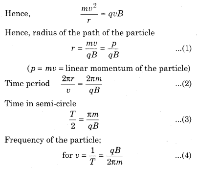
For cyclotron
\(\frac{m v^{2}}{r}\) = qvB
Here m is mass of charge particle, v is velocity of particle, Bis magnetic field.
∴ Radius of the path
r = \(\frac{m v}{q B}\)
Periodic time, T = \(\frac{2 \pi r}{v}=\frac{2 \pi m}{q B}\)
∴ Time spent in semicircle
\(\frac{T}{2}=\frac{\pi m}{q B}\)
Question 12.
Explain the principle of a cyclotron.
Answer:
Principle
Cyclotron works on the principle that a charged particle moving normal to a magnetic field experiences magnetic Lorentz force due to which the particle moves in a circular path. Cyclotron uses the fact that the frequency of revolution of the charged particle in a magnetic field is independent of its energy. Here, the magnetic field moves the charged particles in a circular path and electric field increases their energy in each frequency.
The mathematical principle is given by the Lorentz force in both perpendicular electric and magnetic field :
\(\vec{F}=q \vec{E}+q(\vec{v} \times \vec{B})\)
Question 13.
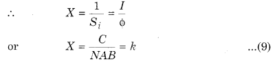
What is the sensitivity and figure of merit of a galvanometer? What is the relation between them?
Answer:
Sensitivity of Galvanometer
That galvanometer is more sensitive; in which a small current when flowing in the coil or small voltage when applied at its ends the necessary deflection is noted.
Figure of Merit of a Galvanometer
The figure of merit of a galvanometer is the current required to produce a deflection of one division in the galvanometer scale. This is inversely proportional to the sensitivity of the galvanometer.
Question 14.
Calculate the resistance of the shunt which is to be connected in parallel to convert a galvanometer into an ammeter of desired range.
Answer:
Shunt
If in any galvanometer current is flowing more than its limit, then the heat generated by the current is so much that it can burn the galvanometer. Apart from this the relative deflection generated due to the current flowing can break the pointer or twist it.
To overcome these difficulties, one attaches a small resistance called shunt, in parallel with the galvanometer coil, so that most of the current passes throught the shunt. Generally, shunt is made up of copper wire; its resistance relative to the galvanometer is very small. Hence by using shunt, the current flowing in the galvanometer can be controlled. Figure (7.37) shows a galvanometer using shunt.
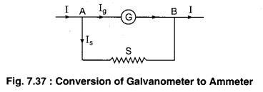
By the use of shunt most of the part of electric current passes through the shunt. Hence, the current flowing through the galvanometer is that much by which it is safe.
If in the figure (7.37) I is the main current and the necessary current in the galvanometer for maximum deflection is Ig then current passing through the shunt S is I – Ig
Since, shunt and galvanometer are attached in parallel hence, there would be same potential difference.
∴ IgG = IsS (G is the resistance of the coil of the galvanometer)
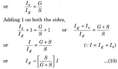
It is clear from equation (10) the value of Ig is \(\left[\frac{S}{S+G}\right]\) part of main current. On the basis of equation (10) expected range galvanometer can be made.
Question 15.
A rectangular current carrying conductor EFGH is shown in the figure which is kept in a uniform magnetic field.
(a) What is the direction of magnetic torque?
(b) When the working torque on the conductor is :
(i) maximum?
(ii) zero?
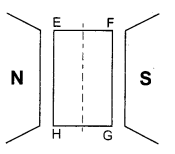
Answer:
(a) According to right hand rule, the direction of magnetic moment will be perpendicular to plane of paper inwards.
(b) (i) When θ = 90°, then
τmax = NIABsin90°
τmax = NIAB
(ii) When θ = 0°
τmin = 0
RBSE Class 12 Physics Chapter 7 Long Answer Type Questions
Question 1.
Explain Biot-Savart’s law. Derive the magnetic field generated by a straight and finite length current carrying conductor with the help of this law. Show that the magnetic field at a perpendicular distance d from an infinite length current carrying conductor is B =\(\frac{\mu_{0} I}{2 \pi d}\)
Answer:
Biot-Savart’s Law
Biot-Savart law was given by French Physicist Biot and Savart on the basis of experiments done by them for the calculation of magnitude of magnetic field at any point due to a current carrying conducting wire. Here, we shall study the relation between current and the magnetic field it produces.
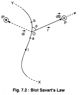
Figure 7.2 shows a conductor wire XY carrying p. current I. Consider an infinitesimal element dl of the conductor. The magnetic field dB due to this element is to be determined at a point P which is at a distance of r from it. Let θ be the angle between dl and the position Fig. 7.2 : Biot Savart’s Law vector r. Direction of vector \(\overrightarrow{d l}\) is in the direction of current.
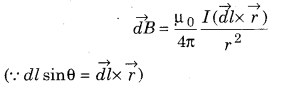
According to Biot-Savart’s Law : The magnitude of the magnetic field \(d \overrightarrow{\mathrm{B}}\) :
i) is directly proportional to the current I.
\(| \overrightarrow{d B |}\) ∝ I ………….. (1)
(ii) is directly proportional to the element length
\(|\overrightarrow{d B |} \propto| \overrightarrow{d l} |\) ……………….. (2)
(iii) is directly proportional to the sine of the angle between vector \(\vec{r}\) and \(\overrightarrow{d l}\) that is sinθ
\(| \overrightarrow{d B |}\) ∝ sin θ ………………. (3)
(iv) is inversely proportional to the square of the distance r.
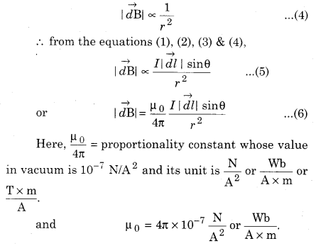
Here, μ is called the permeability of free space (or vacuum). If there is some other medium around the conducting wire, then the magnitude of the magnetic field will be;
\(|\overrightarrow{d B}|=\frac{\mu_{m}}{4 \pi} \frac{I|\overrightarrow{d l}| \sin \theta}{r^{2}}\) ………….. (7)
Where, μ = μ0μr is the permeability of a specific medium; which is dependent on the medium.
∴ μr =\(\frac{\mu_{m}}{\mu_{0}}\) = Relative permeability
Vector form : From equation (7),
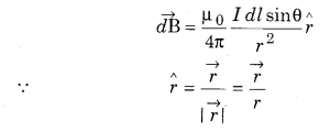
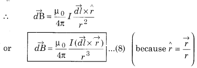
It is clear from the equation (8) that the direction of \(\overrightarrow{d B}\) will be perpendicular to the surface formed by \(\overrightarrow{d l}\) and \(\vec{r}\) and would be up and down depending on the Right Handed Cork Screw Rule. In the figure (7.2) the direction of \(\overrightarrow{d B}\) at point P is downwards perpendicular to the surface, and is represented by (X) sign whereas at point P’ the direction of \(\overrightarrow{d B}\) is outwards perpendicular to the surface of the paper and represented by (.) sign.
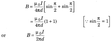
Magnetic Field due to a Straight Current Carrying Wire of Infinite Length
Since, the length of the wire is infinite, hence the ends x and y are at infinite distance. Therefore, the
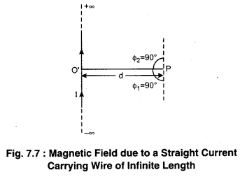
internal angle made by them at point P would be
ϕ1 = ϕ2 = \(\frac{\pi}{2}\)
Therefore, from equation (7) magnetic field due to a straight current carrying wire of infinite length,
Question 2.
Derive the expression for magnetic field at a point situated at the axis of current carrying loop using Biot-Savart’s law in the vector form. Make necessary diagram also.
Answer:
Magnetic Field
We have seen in chapter 1 that a stationary charge sets up an electric field in the space surrounding it and this electric field exerts a force F = qE on the test charge q placed in the magnetic field. If magnetic single poles existed then magnetic field would also be defined by this simple formula. But magnetic single poles do not exist. Hence, we have to use some other method for describing magnetic field. It is very clear by experiments that the force exerted on a test charge by the magnetic field in a stationary position is zero; also that if the test charge is moving parallel to the magnetic field then there is no force exerted on it by the magnetic field. If at any place electric field is absent (and gravitational force is neglected) and at that place a moving test charge experiences a force perpendicular to its velocity then at that place magnetic field \(\overrightarrow{\mathrm{B}}\) is present. Magnetic field is a vector quantity.
Magnetic field can be defined as the magnetic force acting on a charged particle moving in a magnetic field. If q coulomb charge is moving with velocity \(\vec{v}\) in a magnetic field \(\overrightarrow{\mathrm{B}}\) then the force acting on it in the absence of electrcic field is given by following relation :
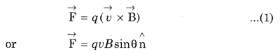
Here, θ is the angle between \(\vec{v}\) and \(\vec{B}\) and \(\hat{\mathrm{n}}\) is the unit vector along the direction of \(\overrightarrow{\mathrm{F}}\).
From equation (1)
\(|\overrightarrow{\mathrm{F}}|\) = qvBsinθ
If θ = 90° then Fmax = qvB
or B = \( \frac{F_{\max }}{q v}\) …………… (2)
In equation (2), if
q = 1 C and v = 1 m/s then
B = Fmax
i. e., “At any place the magnitude of the magnetic field is equal to the resultant force acting on a unit charge moving with a unit velocity at that place when the charge is moving perpendicular to the magnetic field.”
Magnetic field is a vector quantity. Its unit in S.I. system is Weber/m2 which is also called Telsa
Its unit in C.G.S. system is Maxwell/cm2 or Gauss. The relationship between Tesla and Gauss is shown given below;
1 Tesla (T) = 104 Gauss (G)
Dimensional formula of \(\vec{B}\) is [M1L0T-2A-1] .
Magnetic field is also known as intensity of magnetic field or magnetic flux density etc.
Stationary charge only generates electric field. Whereas moving charge generates both electric field and magnetic field.
Magnetic field similar to electric field also follows principle of superposition.
Question 3.
Write the working of cyclotron. Draw the arrangement diagram showing the path of accelerated charged particles (ions) within the Dees A Derive the following parameters off cyclotron :
(i) Frequency of cyclotron
(ii) Kinetic energy of ions in cyclotron.
Answer:
Construction
Cyclotron consists of two-semicircular disc-like metal containers (which are as the letter D), D1 and D2, which are called dees. Figure (a) shows the view of a cyclotron. The diameter of these dees is
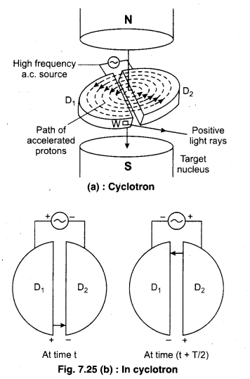
approximately same and are placed at very small interval. The cyclotron uses both electric and magnetic fields in combination to increase the energy of charged particles. As the fields are perpendicular to each other they are called ‘crossed fields’.
Inside the metal boxes the particle is shielded and is not acted on by the electric field. The magnetic field, however acts on the particle and makes it go around in a circular path inside a dee. Every time the particle moves from one dee to another. It is acted upon by the electric field. The whole assembly is evacuated to minimise collisions between the ions and the air molecules. A high frequency alternating voltage is applied to the dees. Magnetic field acts perpendicular to the plane of dees.
Working : A radio frequency oscillator generates approximately 104 V voltage and 106 Hz frequency alternating voltage. Positive ions or positively charged particles (as protons) are released at the centre P. They move in a semi-circular path in one of the dees and arrive in the gap between the dees in a time interval T/2; where T is the period of revolution.
As shown in the figure when any charged particle enters the dees from the ion source then due to the perpendicular magnetic field it does motion in a circular path. Suppose at any instant t, D1 is positive and D2 is negative and positive ion completes its semi-circular path in D1 and moves towards D2 and its energy increases by qV. The time taken by the particle to do motion in D1 is T/2. The alternating voltage in a cyclotron is so adjusted that as any charged particle completes its semicircular path in a dee; the polar effect of the alternating voltage changes. The particle also does motion in a circular path in D2 due to the perpendicular magnetic field. In this way a charged particle does two times motion in a magnetic field in one cycle and its energy increases by 2qV. As energy increases, the radius of the circular path also increases, hence the time period is kept constant.
The frequency of the applied voltage is so adjusted that the polarity of the dees is reversed in the same time that it takes the ions to complete one half of the revolution. The requirement is called resonance condition.
The ions are repeatedly accelerated across the dees until they have the required energy to have a radius approximately that of the dees. They are then deflected by a magnetic field and leave out the system via an exit slit.
Mathematical Analysis
The necessary centripetal force for the circular path of the particle in a cyclotron is obtained from the perpendicular magnetic field;
The value of this frequency should be equal to the frequency of applied alternating voltage. Hence, this is also called cyclotron frequency.
Angular frequency of the cyclotron
ω = 2πv = \(\frac{q B}{m}\) …………. (5)
It is clear from the equation (2), (4) and (5) that the time period, time in semi-circle and angular frequency of charged particle in a cyclotron are constant. (For constant value of B) i.e., they are not dependent on the speed of the particle and radius of the path.
Kinetic energy of the particle
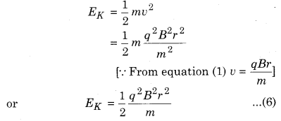
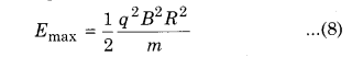
When the radius of the circular path is same as the radius of the dees, then the kinetic energy is maximum of the particle.
Hence, from equation (7);
If total number of circular cycles are N and V is applied potential difference. Gained energy in one complete cycle is 2qV, then the total kinetic energy in N cycles will be :
E = N × energy in one cycle
E = N × 2qV = 2qVN ………… (9)
On comparing equations (8) and (9)
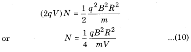
Question 4.
Obtain the expression for force acting on the current conductor in magnetic field. Give the right hand palm rule for the direction of this force.
Answer:
Force on Current Carrying Conductor in a Magnetic Field
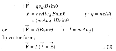
When a conducting wire is kept in a uniform magnetic field then the free electrons (in the conducting particle) flow with velocity vd and experience Lorentz force \(\overrightarrow{\mathrm{F}}=q\left(\overrightarrow{v_{d}} \times \vec{B}\right)\). Hence, a resultant force works on the conductor.
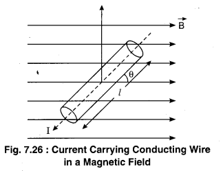
According to the figure suppose the length of the current carrying conductor is l and the cross-sectional area is A. The number of electrons in the unit volume of the conductor is n. Hence, total charge in the conductor is q = neAl.
\(\overrightarrow{\mathrm{F}}=I(\vec{l} \times \overrightarrow{\mathrm{B}})\) …………. (1)
Suppose, I magnitude current is flowing in the conductor; and conductor rod makes an angle θ with the magnetic field \(\overrightarrow{\mathrm{B}}\) .
If the free electrons are moving with speed vd then magnitude of magnetic force on them
Here, the direction of \(\vec{l}\) is in the direction of the current of the conductor.
It is clear from the equation (2) that the direction of force on the current carrying conductor is perpendicular to the plane formed by \(\vec{l}\) and \(\overrightarrow{\mathrm{B}}\)
(according to Right Hand Screw Rule).
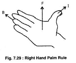
Right Hand Palm Rule : According to Right Hand Palm Rule if we stretch our right hand palm in such a way that the thumb points in the direction of electric points in the direction of electric current I and the fingers points towards magnetic field \(\overrightarrow{\mathrm{B}}\); then the force acting on the conductor \(\overrightarrow{\mathrm{F}}\) will be perpendicular to the palm as shown in the figure (7.29).
Question 5.
Derive the expression for force and torque acting on the current carrying coil placed in magnetic field. Give necessary diagram. When the torque will be maximum and minimum?
Answer:
Force and Torque on a Current Carrying Rectangular Loop in Uniform Magnetic Field
Suppose ABCD is a rectangular loop, in which current I is flowing in anticlockwise direction. Loop is situated in a uniform magnetic field \(\overrightarrow{\mathrm{B}}\) and the rotational axis of the loop is perpendicular to \(\overrightarrow{\mathrm{B}}\). Length of the loop is l and breadth is b. (Figure 7.32.)
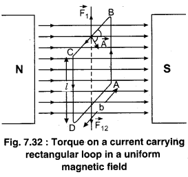
Suppose, at any instant the vector area \(\overrightarrow{\mathrm{A}}\) (perpendicular drawn at the plane conducting loop makes an angle θ with the magnetic field \(\overrightarrow{\mathrm{B}}\). All the four sides of the loop behave as a current carrying conductor in the magnetic field. Hence, magnetic force will work on them. On all the sides the magnetic force is calculated as follows.
(i) Force on side BC : Since BC = b, hence the force \(\overrightarrow{\mathrm{F}}_{1}=I(\overrightarrow{\mathrm{b}} \times \overrightarrow{\mathrm{B}})\). The direction of \(\overrightarrow{\mathrm{F}}_{1}\) is given by right hand screw rule and is vertically upwards.
(ii) Force on side DA : Force \(\overrightarrow{\mathrm{F}}_{2}=I(\overrightarrow{\mathrm{b}} \times \overrightarrow{\mathrm{B}})\) will act on this side, whose direction will be vertically downwards.
(iii) Force on side AB : The length of the side BC is l and this side is perpendicular to the magnetic field.
Force on this;
\(\overrightarrow{\mathrm{F}}_{3}=I(\overrightarrow{\mathrm{b}} \times \overrightarrow{\mathrm{B}})\)
\(\left|\overrightarrow{\mathrm{F}}_{3}\right|\) = IlBsin90° = IlB
The direction of \(\overrightarrow{\mathrm{F}}_{3}\) is perpendicular to the plane
of the paper and inwards.
(iv) Force on the side CD : This side is also perpendicular to \(\overrightarrow{\mathrm{B}}\) and CD = l. Therefore, force on this;
\(\overrightarrow{\mathrm{F}_{4}}=I(\overrightarrow{\mathrm{l}} \times \overrightarrow{\mathrm{B}})\)
\(\left|\overrightarrow{\mathrm{F}}_{4}\right|\) = IlB
The direction of \(\overrightarrow{\mathrm{F}}_{4}\) is perpendicular to the plane of the paper and outwards.
Hence, it is clear that the forces \(\overrightarrow{\mathrm{F}}_{1}\) and \(\overrightarrow{\mathrm{F}}_{2}\) working on the loop are along the rotational axis of the loop but in opposite direction, hence they cancel out each other. As a result there is no vertical displacement in the loop. Also \(\overrightarrow{\mathrm{F}}_{1}\) and \(\overrightarrow{\mathrm{F}}_{2}\) are linear hence there is no torque generated by them.
Forces \(\overrightarrow{\mathrm{F}}_{3}\) and \(\overrightarrow{\mathrm{F}}_{4}\) are also same in magnitude but opposite in direction, hence their resultant force is also zero. But the line of action of those forces is different and these forces are working at a distance b. Therefore, they together force a couple torque which tries to rotate the loop in anti clockwise direction.
In this way the resultant force on a rectangular loop of all the forces acting is zero.
\(\overrightarrow{\mathrm{F}}=\overrightarrow{\mathrm{F}}_{1}+\overrightarrow{\mathrm{F}}_{2}+\overrightarrow{\mathrm{F}}_{3}+\overrightarrow{\mathrm{F}}_{4}=0\)
Hence, there is no type of transfer motion in the loop.
Question 6.
Write Ampere’s law. Obtain the expression for magnetic at the axis of long solenoid giving the necessary diagram.
Answer:
Ampere’s Circuital law : According to Ampere’s circuital law, “Line integral of magnetic field around a closed curve is equal to times the net current passing through the closed curve.” Mathematically it can be written as given below :
\(\oint \vec{B} \cdot \overrightarrow{d l}=\mu_{0} \Sigma I\) ………….. (1)
Magnetic field at the axis of current carrying solenoid :
A solenoid is a coil of enameled or insulated wire in a corkscrew shape wrapped around a rod-shaped armature usually made of Iron. The solenoid’s length is large compared to its radius. It consists of a long wire would in the form of a helix where the neighbouring turns are closely spaced. So each turn can be regarded as a circular loop.
The turns of the wire in a solenoid are uniformly wounded around, its length in which the plane of each turn is approximately perpendicular to the surface of the solenoid. When constant current flows through the solenoid magnetic field is generated. The plane of each turn of an ideal solenoid is perpendicular to the axis of the solenoid.
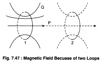
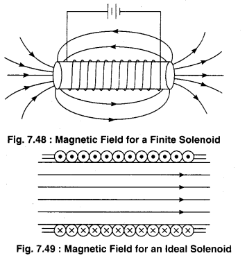
To understand the magnetic field generated by a solenoid help can be taken from the magnetic field of any current carrying coil. Figure (7.48) shows two similar current carrying conductor loops in which same current is flowing and the magnetic field generated by them. It can be seen here that for points (like P) which are on the axis or close to the axis, the magnetic field direction is in same direction for both the coils but for points (like Q) which are at the distance from the axis the fields are in opposite directions. A solenoid can be taken as a group of many such circular turns. Figure (b) shows the magnetic field lines for a finite solenoid. In which the magnetic field is in the same direction whereas oppose each other. In this way, magnetic field on the outside points is weak. As the turns as closer this behaviour increases hence for an ideal solenoid, it is assumed that the magnetic field inside it is uniform althrough and outside it is zero.
Question 7.
Obtain the expressions for sensitivity and figure of merit of galvanometer giving its principle. On what factors does it depend?
Answer:
Sensitivity of Galvanometer
That galvanometer is more sensitive; in which a small current when flowing in the coil or small voltage when applied at its ends the necessary deflection is noted.
Current Sensitivity
The current sensitivity of the galvanometer is the deflection per unit current. It is measured in div./amp.
From equation 2;
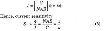
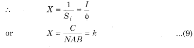
It is clear from the equation (5) that to increase the current sensitivity of the galvanometer the cross sectional area A of the coil, number of turns N of the coil and the magnetic field B has to be more and the value of C has to be less. The value of N, A and B cannot be increased more because due to this the weight of the coil will increase. .
Hence, to increase the sensitivity it is more relevant to decrease the value of C.
Since, C = \(\frac{\pi \eta r^{4}}{2 l}\)
where, η is the elasticity constant of the substance of the wire, r is the radius of the wire and l is the length of the wire.
For Phosphor-Bronze the value of r| is less. Hence, to increase the current sensitivity of the Galvanometer a thin long wire of Phosphor-Bronze is used. But due to the thin suspended wire there is more risk of breaking, hence this galvanometer is not portable.
Voltage Sensitivity
Voltage sensitivity is defined as the deflection per unit voltage. Hence, voltage sensitivity;
VS = \(\frac{\phi}{V}\) …………….. (6)
If G is the resistance in the coil of the galvanometer and I is the current flowing then;
V = IG
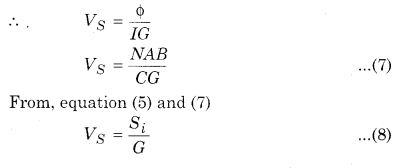
Figure of Merit of a Galvanometer
The figure of merit of a galvanometer is the current required to produce a deflection of one division in the galvanometer scale. This is inversely proportional to the sensitivity of the galvanometer.
RBSE Class 12 Physics Chapter 7 Numerical Questions
Question 1.
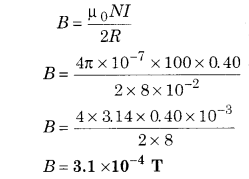
There are 100 turns in a circular coil of a wire, the radius of each is 8.0 cm and in this 0.40A current is flowing. What will be the magnitude of the magnetic field at the centre of the coil?
Solution:
Number of turns in coil N = 100
Radius R = 8.0cm = 8 × 10⁻² m
Flowing current I = 0.40A
Magnetic field at the centre of coil
Question 2.
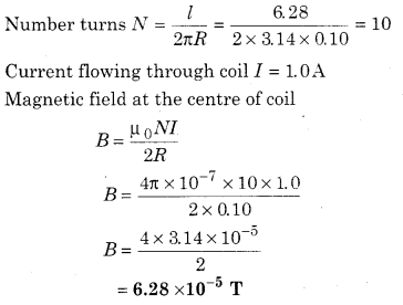
A coil of radius 0.10 m is made from a long wire 6.28 m in which a current 1.0 A is flowing. Calculate the value of magnetic field at its centre.
Solution:
Length of wire to make coil / = 6.28 m
Radius of coil R = 0.10 m
Question 3.
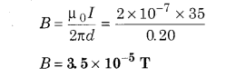
35 A current is flowing in long straight wire. Calculate the magnetic field at a point which is at a distance 20 cm from the wire.
Solution:
Current flowing in conducting wire I = 35A
Distance from wire r = 20 cm = 0.20 m
Intensity of magnetic field on point
Question 4.
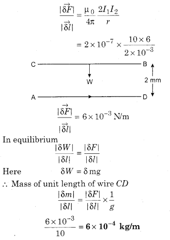
10 A current is flowing through a wire AB. This wire is horizontally placed on a table. Another wire CD is just above the wire AB at 2 mm height. 6 A current is flowing through the wire CD. What should be the mass of the wire CD per unit length so that in free state it hangs at its place? Relative to the wire AB what would be the direction of electric current in CD ? (g = 10 m/s2)
Solution:
Force acting on unit length of wire due to AB
Question 5.
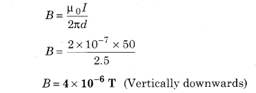
A long and straight wire kept in horizontal plane has an electric current 50 A flowing through it. Calculate the magnitude of the magnetic field at a point 2.5 m distance towards west. Also calculate the direction.
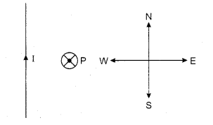
Solution:
Current flowing in wire, I = 50 A
Distance of point P from wire, d = 2.5 m
Intensity of magnetic field at point P
Question 6.
Two long parallel wires are 4 cm apart. In them current I and 31 are flowing in the same direction. Where would be the magnetic field generated by both should be zero?
Solution:
Let at point P magnetic field is zero.
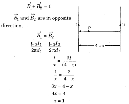
So, at the distance of 1 cm from the current carrying wire, the net magnetic is zero.
Question 7.
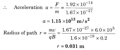
A proton of magnetic field 0.2 T enters a magnetic field perpendicular with a velocity = 6.0 × 10⁵ m/sec. Calculate the acceleration of the proton and radius of the path.
Solution:
Given,
Magnetic field B = 0.2T
Speed of proton v = 6.0 × 10⁵ m/s
Charge q = e = 1.6 × 10⁻¹⁹ C
θ = 90° ‘
∴ F = qvBsinθ
F = 1.6 × 10-19 × 6.0 × 105 × 0.2 × sin90°
F = 1.92 × 10⁻¹⁴ N
∵ F = ma
Question 8.
A wire in which 8 A current is flowing is kept in a uniform magnetic field 0.15T and makes an angle 30° with the field. Calculate the magnitude of force and direction which is acting on unit length.
Solution:
Given,
Current flowing through wire I = 8 A
Magnetic field B = 0.15 T
θ = 30°
∴ Force acting on current carrying wire
F = I/B sinθ
Here l = 1 m, then force acting on unit length
F = \(\frac{F}{l}\) = 8 × 0.15 × sin30°
F = 8 × 0.15 × \(\frac{1}{2}\)
F = 0.6 N/m
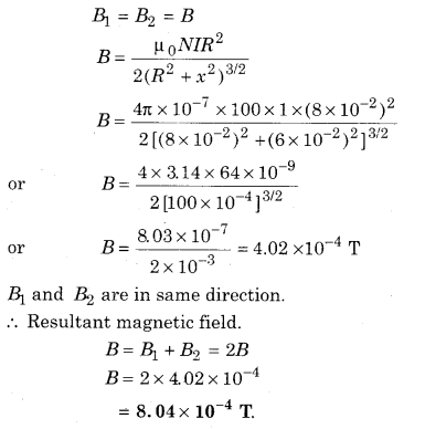
Question 9.
Two similar coils of radius 8 cm and number of coils = 100 are parallely placed. The distance between their centres is 12 cm. If 1 A current flows in the same direction in both the coils then calculate the value of magnetic field on the axis right in the middle.
Solution:
Radius of each coil R = 8cm = 8 × 10⁻² m
Number of turns N = 100
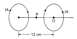
Magnetic field at mid point the line joining two
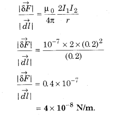
Question 10. Two 2 m long parallel wires are placed in vacuum at a distance 0.2 m. If current 0.2 A flows in both the wires in the same direction, calculate the force acting per unit length of the coil.
Solution:
Given,
l1 = l2 = 2 m
r = 0.2 m
Following current I1 = I2 = 0.2 A
Force acting on unit length
Question 11.
A square coil whose each side is 10 cm has 20 turns and 12 A current is flowing. The coil is hanging vertically and a perpendicular drawn from the plane of this makes an angle 30° with the uniform magnetic field of 0. 80 T. How much is the magnitude of torque acting on the coil?
Solution:
Side of square coil = 10 cm
∴ Area of coil A = (10)2 = 100cm2 = 10-2 m2
Current flowing I = 12 A
Number of turns in coil N = 20
Magnetic field B = 0.80 T
Angle θ = 30°
Torque acting on coil τ = NIABsinθ
τ = 20 × 10-2 × 12 × 0.80 x× sin 30°
τ = 20 × 12 × 0.80 × \(\frac{1}{2}\) × 10-2
τ = 0.96 N-m.
Question 12.
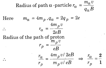
With the similar velocity v some α particles and some protons enter perpendicular to uniform magnetic field. These particles make a circular and linear path. How much is the ratio of the radii of these paths?
Answer:
Question 13.
A cyclotron’s dee radius is 0.5 m and, 1. 7 T cross-sectional magnetic field is working. Calculate the maximum kinetic energy gained by the proton.
Solution:
Radius of dee R = 0.5 m
Magnetic field B = 1.7 T
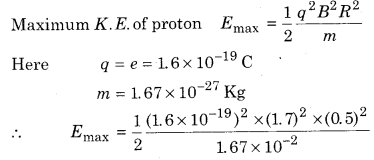
Question 14.
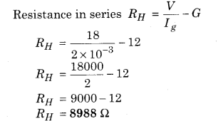
The necessary current for full scale deflection is 0.2 mA for any galvanometer of resistance 12 Ω. How will you convert it to a voltmeter of range 0 to 18 V?
Solution:
Resistance of coil G = 12 Ω
Range of desired voltmeter V = 19 V
Deflecting current for full scale Ig = 2 mA
To convert galvanometer into an voltmeter, a high resistance is to be added in series.
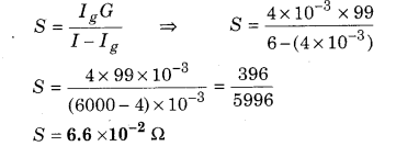
Question 15.
The necessary current for full scale deflection is 4 mA for any galvanometer of resistance 99 Ω. What would you do to convert it to an ammeter of range 0 to 6A?
Solution:
Given G = 99 Ω
Current at full deflection = 4 mA,
Range of Ammeter I = 6 A
To connect a galvanometer into an ammeter, a low resistance is to added in parallel.
Question 16.
A solenoid of length 1.0 m has 100 turns and as radius 1 cm. 5 A current is flowing in the solenoid. Calculate the axial magnetic field. If an electron moves along its axis with the velocity 104 m/s, then how much force will it experience?
Solution:
Length of solenoid l – 1.0 m
Radius of solenoid = 1 cm = 10 m, flowing current I = 5 A, Number of turns N = 100
Axial magnetic field in solenoid
B = \(\mu_{0} \frac{N}{l} I\)
B = 4π × 10-7 × \(\frac{100}{1.0}\) × 5
B = 4 × 3.14 × 5 × 10-5
B = 6.28 × 10⁻³ T along axial direction
If electron moves with velocity 104 m/s along its axis, then the angle between magnetic field and velocity will be O.
From, F = qvBsinθ (θ = 0°)
Question 17.
In a solenoid of 0.5 m long the wires are wounded around. In every layer the number of turns is 500. If its radius is 1.4 cm and 5 A current is flowing in it, then calculate the value of magnetic field at its centre.
Solution:
Length of solenoid l = 0.5 m.
Number of turns N = 2 × 500 = 1000
Flowing current I = 5A
Magnetic field produced at centre
B = \(\mu_{0} \frac{N}{l} I\)
B = 4π × 10-7 × \(\frac{100}{0.5}\) × 5
B = 4 × 3.14 × 10 -7 × 104
B = 12.56 × 10⁻³ T