Rajasthan Board RBSE Class 10 Science Notes Chapter 10 Electricity Current
Electricity:
Electricity can be defined as the form of energy which is produces due to presence of electric charge.
Electric Current:
The rate of flow of charge is called electric current. If charge Q flows through a point in time t then;
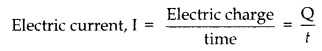
At any point in an electric circuit if n electrons pass in time t then n’ charge passes through that point in time t. In this situation, electric current can be given by following equation:
\(I=\cfrac { nc }{ t } \)
Where; e is the charge on electron which is equal to 1.6 x 10⁻¹⁹ Coulomb.
![]()
If 1 C charge passes through a point in an electric circuit in 1 s then the value of electric current in the circuit is 1 ampere. Ammeter is the instrument used for measuring electric current and it is connected in series in the circuit.
Electric potential shows the direction of electric charge in a charge object. When two charge objects are kept in contact with each other then positive charge always flows from high potential to low potential.
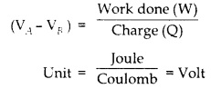
The work done in carrying one unit charge from one point to another point in an electric circuit is equal to potential difference between two points. Hence, potential difference between two points A and B.
Electric Potential:
If B is supposed to be at infinity then,
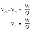
If Q = 1 then VA = W , thus, potential can be defined as work done in carrying unit charge from infinity to a point.
Potential difference is measured by an instrument called voltmeter. A voltmeter is connected in parallel across two points between which potential difference is to be measured.
As per Ohm’s Law, “Under constant physical conditions of conductor; like temperature, pressure, length, area of cross section, etc. the potential difference between two ends of a conductor is directly proportional to electric current flowing through it.”
Vα I
V = RI
Here; R is the constant of proportionality and is called the resistance of conductor.
Unit of potential difference is volts and that of current is ampere, so unit of resistance can be given by following equation.
![]()
Definition of 1 Ohm:
If the current of 1 ampere through a conductor produces the potential difference of 1 volt between its two points then resistance of conductor is called 1 Ohm.
Resistance :
The obstacle against flow of charge through a conductor is called resistance. Since resistance is inversely proportional to conductivity hence higher the resistance lower is the conductivity.
Dependence of Resistance:
Resistance is directly proportional to length of wire and inversely proportional to area of cross section.

Here; K is the constant of proportionality which called specific resistance or resistivity of conductor. The unit of resistivity can be calculated as follows:
![]()
Resistivity:
The resistance of a wire of unit length and unit area of cross section is called specific resistance or resistivity. The resistivity does not depend on length or area of cross section rather on the material of conductor.
![]()
Dependence of Resistance on Temperature:
Resistance of some metals increases with increase in temperature like gold, silver, copper, etc. Resistance of some alloys experience negligible change with change in temperature, e.g. manganin and constant an. But in some metals, resistance decreases with increase in temperature, e.g. silicon and germanium. Such metals are called semiconductor. In some metals, resistance becomes zero when temperature is reduced to a certain point. Such metals are called super conductor. For example, resistance of mercury
becomes zero at 42 K.
Combination of Resistances :
Resistors are combined in two ways, viz. series Combination and parallel combination.
- Series Combination:
In this type of combination, second end of first wire is connected to first end of second wire, second end of second wire is connected to first end of third wire, on so on. Equivalent resistance of a series combination of different resistors is equal to sum of individual resistances.
R = R1+ R2+ R3 - Parallel Combination:
In this combination, one end of each resistor is connected at a single point and another end of each resistor is connected at another point. In parallel combination, the reciprocal of equivalent resistance is equal to sum of reciprocals of individual resistances.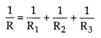
Thermal Effect of Electric Current:
If a pure resistor is connected in a circuit then almost all the energy from the battery (or source of current) is lost in the form of heat. This effect is called thermal effect of electric current. This is also called heating effect of electric current. This effect is utilized in electric heater, electric iron and geyser.
If charge Q is flowing through the wire in t second when potential difference is V then work done in carrying Q charge in t time is;
W = QV = ItV [ ∴Q = It]
The energy spent by source in time t would convert into heat energy. Hence, heat energy produced in time t is,
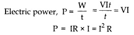
H = Vlt = IR x it [ V = IR]
Or, H = I2 Rt
Thus, heat produced in conducting wire is directly proportional to square of current through wire, resistance of conductor, and time.
Electric Power:
The work done in unit time by current through a circuit is called electric power.
Unit of power is Joule per second. This is also called Watt.
1 k W=1000 W = 103 W 1
MW=1000000 W = 106
W 1 horse power (hp) = 746 W
As electric energy is equal to product of electric power and time hence,
Electric energy = P x f
The unit of electric energy is Watt hour (Wh). When 1 W of electric power is used for 1 hour then 1 Wh energy is used. The commercial unit of electric energy is kilo Watt hour (kWh) which is generally called as unit.
Magnetic Effect of Electric Current:
Hans Christian Oersted observed that when electric current flows through a conducting wire then a magnetic field is produced around the wire.
Direction of Magnetic Field :
There are two laws to know the direction of magnetic field due to current in a conductor. These are as follows:
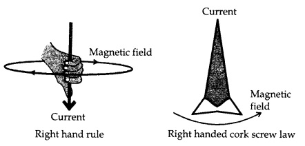
Right Hand Rule:
When the right hand thumb is kept straight and remaining fingers are kept as if wrapped around ket as if wrapped around
the thumb, the direction of thumb shows the direction of current and direction of other fingers shows the direction of magnetic field.
Maxwell’s Cork Screw law:
When a screw is turned so that it moves forward then direction of forward movement of screw shows the direction of current and direction of rotation of screw shows the direction of magnetic field.
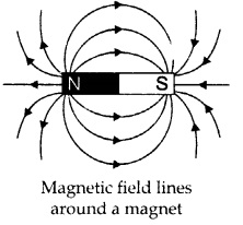
Magnetic Field Lines :
Some properties of magnetic field lines are as follows:
- Magnetic field line goes from north pole to south pole, when outside the magnet.
- Magnetic field line goes from south pole to north pole, when inside the magnet.
- Magnetic field lines appear as concentric lines and no two lines intersect each other.
- Magnetic field lines are closer to each other when they are near the magnet but become farther from each other when they are far
- from the magnet, Closeness of field lines shows the strength of magnetic field.
Electromagnetic Induction:
When a bar magnet and a coil are in relative motion to each other then electric current is induced in the coil. This induction of electric current in a coil is called electromagnetic induction. To obtain electromagnetic induction, either the coil or the magnet should be moved.
Magnetic Flux:
When a surface is kept in a magnetic field then number of magnetic field lines passing throjagh that surface is called the magnetic flux of that surface. The unit of magnetic flux is Weber (Wb).
Electric Current Generator :
It is a device which works on the principle of electromagnetic induction. The coil in a generator is rotated with the help of mechanical energy to produce electric current. Electric generators are of two types, viz. A. C. generator and D. C. generator.
AC Generator:
AC generator is a device which converts mechanical energy into AC electric current. “When direction of current keeps on changing, it is called alternating current or AC Current.” There are four main parts in an AC generator, viz. field magnet, armature, slip ring and breshs
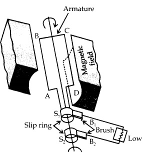
Field Magnet:
This is a very powerful magnet; as shown by NS in given figure.
Armature:
This is composed of a rectangular coil PQRS which has insulated copper wire wound around a frame of cast iron.
Slip Ring:
Two metallic rings S1 and S2, are connected respectively to the ends A and D of coil. These rings rotate along with rotation of coil,
Brushes:
These are made of carbon or any metal.
One end of brushes touches the slip ring while another end touches other part of the circuit.
Working of AC Generator:
When armature moves then magnetic flux through ABCD changes continuously. This induces current at the ends of the coil. When coil is rotated clockwise then the plane of coil keeps on alternatively becoming perpendicular and parallel to the magnetic field. As magnetic flux reduces in first half cycle, the direction of current is clockwise in external circuit during the first half cycle. This means that during the first half cycle, current moves from B1 to B2. In the next half cycle, current moves from B2 to B1. Thus, direction of current keeps on changing after every half cycle of the armature.
DC Generator:
When direction of current remains the same, it is called direct current. A device which converts mechanical energy into direct current is called DC generator.
Construction:
The construction of DC generator is almost same as AC generator. The only difference is presence of split rings (DC Generator) in place of circular rings (AC Generator). The split ring works as commutator.
- The split ring is a metallic ring with two equal parts, i.e. C, and C2. One end of armature is connected to one part of C1 while another end of armature is connected to another part of C1. The splits rings C, and C2 touch the brushes B1 and B2.
- Working of Commutator: When armature is rotated in the magnetic field then electric current is induced in armature. The position of brushes B1 and B2 is coordinated in such a way that after every half cycle of armature, the brushes keep on changing connections from one split ring to another split ring. This helps in maintain the current in a single direction even after each half cycle of armature.